- 您现在的位置:买卖IC网 > PDF目录43903 > LC7153M PLL FREQUENCY SYNTHESIZER, 160 MHz, PDSO24 PDF资料下载
参数资料
| 型号: | LC7153M |
| 元件分类: | PLL合成/DDS/VCOs |
| 英文描述: | PLL FREQUENCY SYNTHESIZER, 160 MHz, PDSO24 |
| 封装: | MFP-24 |
| 文件页数: | 9/11页 |
| 文件大小: | 279K |
| 代理商: | LC7153M |
LC7153, 7153M
No.4160–7/11
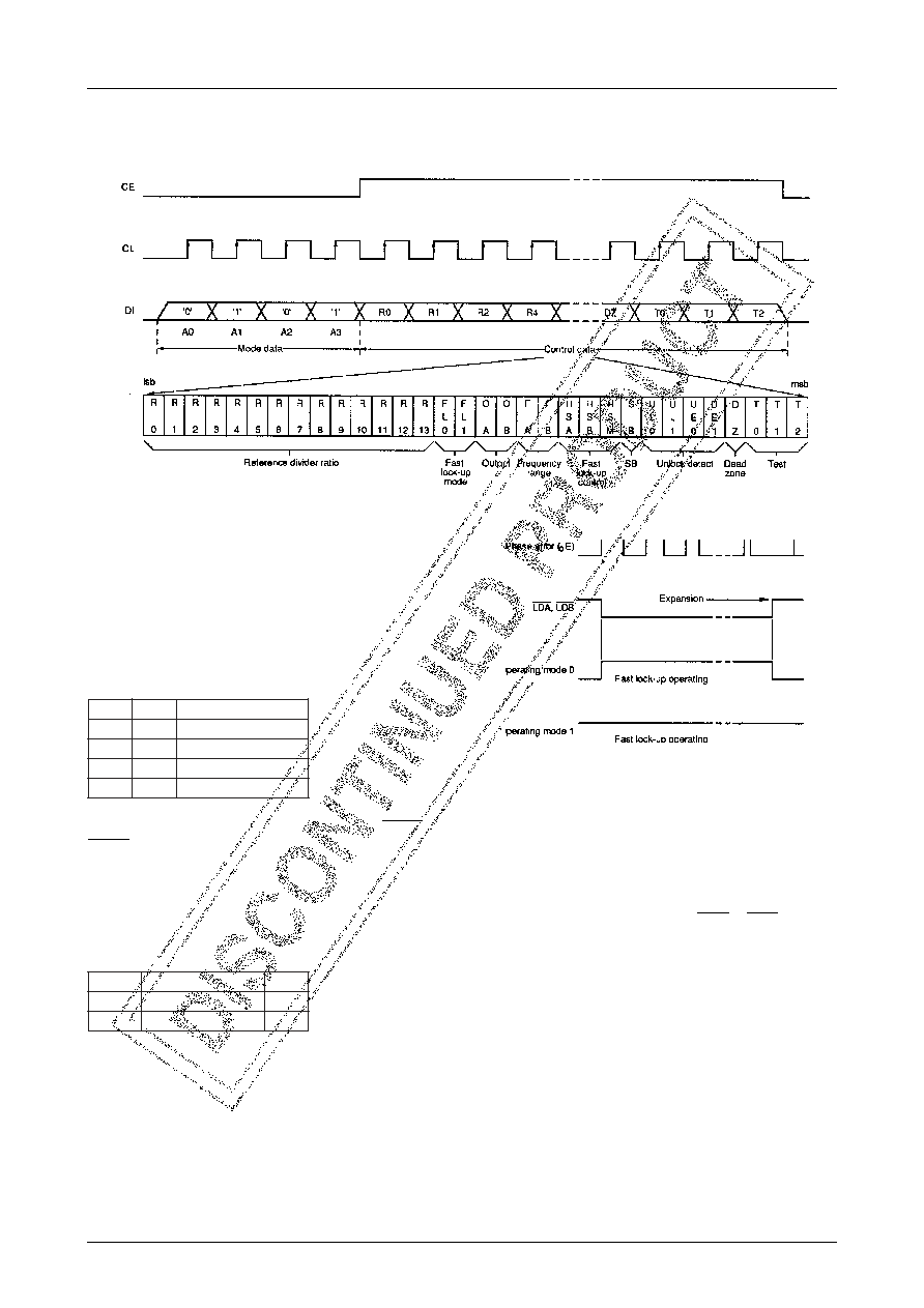
Mode 2 command format and functions
The Mode 2 command comprises the data bits which de-
termine the reference frequency divider ratio and control
functions. The command format is shown in figure 3. Bit
R0 is the first bit received.
Bits R0 to R13 determine the reference divider ratio. The
range of allowable divider ratios is NR=8 (0008H) to 16383
(3FFFH).
Bits FL0 and FL1 are the fast lock-up mode select bits.
The fast lock-up modes are shown in table 2. The higher
the mode number, the greater the expansion width of the
detected phase error signal.
Bits OA and OB are the uncommitted output control bits.
They are latched and then inverted to control OUTA and
OUTB, respectively. If either bit is 1, the open-drain out-
put is pulled LOW.
Bits FA and FB are the input frequency range select bits.
The PIA and PIB frequency ranges, set by FA and FB, re-
spectively, are shown in table 3.
Table 3. Frequency ranges
Bits HSA, HSB and HSM are the fast lock-up control bits.
When HSA or HSB=1, the fast lock-up circuits for PLLA
or PLLB, respectively, are ON. When HSA or HSB=0, the
respective circuits are OFF. For use with FM, the fast lock-
up circuits should be OFF. HSM determines the fast lock-
up operating mode. When HSM=0, operating mode 0 is
selected and the fast lock-up only operates when the PLLs
are unlocked. When HSM=1, operating mode 1 is selected
and the fast lock-up operates normally, as shown in figure
4.
Figure 3. Mode 2 command (reference divider and control data)
0
L
F1
L
Fe
d
o
m
p
u
-
k
c
o
l
t
s
a
F
00
0
10
1
01
2
11
3
B
F
,
A
Fe
g
n
a
r
y
c
n
e
u
q
e
r
f
t
u
p
n
It
i
n
U
00
.
0
4
o
t
5
.
1z
H
M
10
6
1
o
t
5
3z
H
M
Figure 4. Fast lock-up operating modes
Bit SB is the standby mode control bit. When SB=1, standby
mode is selected. In standby mode, PLLB is stopped, PIB
is pulled LOW, and PDB1 and PDB2 are high impedance.
When SB=0, normal operation is selected.
Bits UL0 and UL1 determine the unlock detection thresh-
old. The PLL unlock detector output, LDA or LDB, is pulled
LOW when the phase differential between the reference
and the divider inputs exceeds the threshold set by UL0
and UL1. The threshold for different crystal frequencies is
shown in table 4, and the threshold for other frequencies
can be calculated. The threshold is common to both PLLs.
Note that a PLL will temporarity lose lock when either UL0
or UL1 is changed.
相关PDF资料 |
PDF描述 |
|---|---|
| LC72121M | PLL FREQUENCY SYNTHESIZER, 160 MHz, PDSO24 |
| LC72121 | PLL FREQUENCY SYNTHESIZER, 160 MHz, PDIP22 |
| LC72121V | PLL FREQUENCY SYNTHESIZER, 160 MHz, PDSO24 |
| LC72121M | PLL FREQUENCY SYNTHESIZER, 160 MHz, PDSO24 |
| LC72131M | PLL FREQUENCY SYNTHESIZER, 40 MHz, PDSO20 |
相关代理商/技术参数 |
参数描述 |
|---|---|
| LC717A00AJ | 制造商:SANYO 制造商全称:Sanyo Semicon Device 功能描述:Capacitance-Digital-Converter LSI for Electrostatic Capacitive Touch Sensors |
| LC717A00AJ-AH | 功能描述:电容触摸传感器 TOUCH SENSOR IC RoHS:否 制造商:Microchip Technology 电源电压: 通道数量: 封装 / 箱体: 尺寸: 温度范围: |
| LC717A00AR | 制造商:SANYO 制造商全称:Sanyo Semicon Device 功能描述:Capacitance-Digital-Converter LSI for Electrostatic Capacitive Touch Sensors |
| LC717A00ARGEVB | 功能描述:数据转换 IC 开发工具 EVM FOR LC717A00AR RoHS:否 制造商:Texas Instruments 产品:Demonstration Kits 类型:ADC 工具用于评估:ADS130E08 接口类型:SPI 工作电源电压:- 6 V to + 6 V |
| LC717A00ARGEVK | 制造商:ON Semiconductor 功能描述:EVAL BD FOR LC717A00ARGEVK - Bulk 制造商:ON Semiconductor 功能描述:IC TOUCH SENSOR CAP-DGTL VCT28 |
发布紧急采购,3分钟左右您将得到回复。