- 您现在的位置:买卖IC网 > PDF目录30730 > LC723341E SPECIALTY CONSUMER CIRCUIT, PQFP64 PDF资料下载
参数资料
| 型号: | LC723341E |
| 元件分类: | 消费家电 |
| 英文描述: | SPECIALTY CONSUMER CIRCUIT, PQFP64 |
| 封装: | 14 X 14 MM, 0.80 MM PITCH, QIP-64 |
| 文件页数: | 11/11页 |
| 文件大小: | 114K |
| 代理商: | LC723341E |
LC723341E
No.8013-9/11
Continued from preceding page.
Pin No.
Symbol
I/O
Description
Equivalent circuit
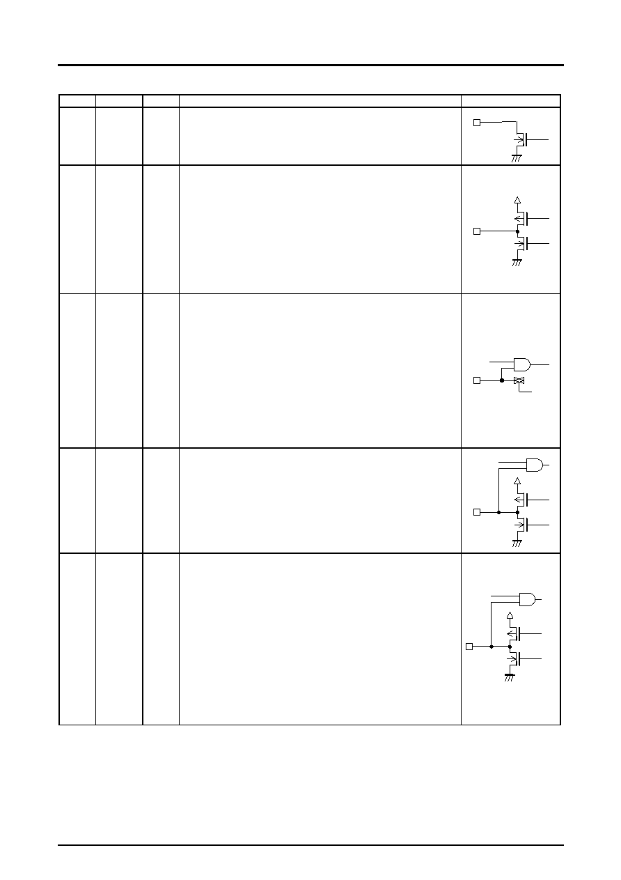
20
PE2
O
PE2 is an open-drain output port. A pull-up resistor between this port and VDD is required.
In backup mode, PE2 goes to the high-impedance state. After a reset, it remains at the low
level until an output instruction is executed.
N-channel open-drain output
18
PE3/BEEP
O
General-purpose output or beep tone output shared-function port.
The BEEP instruction is used to switch between the general-purpose output and beep tone
output functions.
To use this port as a general-purpose output port, execute a BEEP instruction with b3 = 0 to
set up the general-purpose output function. If b3 = 1, the beep tone output function will be
selected. Bits b0, b1, and b2 select the beep tone frequency. The LC723341E provides
seven beep tone frequencies.
*:
When the PE3 port is set to the beep tone function, executing an output instruction only
switches the state of the internal output latch and has no effect on the beep tone output.
In backup mode, this port goes to the high-impedance state. This state is maintained until
either an output instruction or a BEEP instruction is executed.
After a reset, the general-purpose output port function will be selected.
CMOS push-pull output
24
23
22
21
PF0/ADI0
PF1/ADI1
PF2/ADI2
PF3/ADI3
I
General-purpose input or A/D converter input shared-function ports. The IOS instruction
(PWn = FH, b0 to b3) is used to switch between the general-purpose input and A/D
converter input functions. The function can be switched in 1-bit units. (0: general-purpose
input, 1: A/D converter input)
When the A/D converter input function is selected, the pin to be A/D converted is selected
with the IOS instruction (PWn = 1). The A/D converter is started with the UCC instruction (b3
= 1, b2 = 1). The ADCE flag is set when the conversion completes. The INR instruction is
used to read out the data.
*:
Since CMOS input is disabled, the data read out will always be zero if an input
instruction is executed for a port pin set to analog input mode.
Execute an IOS instruction (PWn = 0, b0 to b3) to set the port that clears backup mode.
In backup mode, this port goes to input disabled high-impedance state. After a reset, the
general-purpose input port function will be selected. The conversion time for the 6-bit
successive approximation A/D converter is 0.64 ms. The A/D converter full-scale voltage is
63/96 of VDD.
CMOS input or analog input
28
27
26
PK0
PK1
PK2
I/O
These are general-purpose I/O ports. *1
The IOS instruction (PWN = A) is used to switch between the general-purpose input and
output port functions. The I/O direction can be set in 1-bit units. (0: input, 1: output)
In backup mode, this port goes to the input disabled high-impedance state.
After a reset, the general-purpose input port function will be selected.
CMOS push-pull circuit
32
31
30
29
36
35
34
33
S17/PG0
S18/PG1
S19/PG2
S20/PG3
S13/PH0
S14/PH1
S15/PH2
S16/PH3
I/O
LCD driver segment output or general-purpose I/O shared-function ports. *1
The IOS instruction is used to switch between the segment output and general-purpose I/O
functions and for I/O direction switching for the general-purpose port function.
When used as segment output ports
PG port ... IOS instruction (PWn = B, b0 to b3) 0: Segment output
PH port ... IOS instruction (PWn = C, b0 to b3) 0: General-purpose I/O
These pins can be switched in 1-bit units.
When used as general-purpose I/O ports
PG port ... IOS instruction (PWn = 6, b0 to b3) 0: Input
PH port ... IOS instruction (PWn = 7, b0 to b3) 1: Output
The I/O directions of these pins can be set in 1-bit units.
In backup mode, when used as general-purpose output ports, the pins go to the input
disabled high-impedance state. When used as segment outputs, these pins will be held
fixed at the low level.
After a reset, the segment output function will be selected.
CMOS push-pull circuit
Note:
1 When ports that can be switched between input and output are used as output ports, the output data must be established in advance with an OUT,
SPB, or RPB instruction before the port is set to output mode with an IOS instruction.
Continued on next page.
相关PDF资料 |
PDF描述 |
|---|---|
| LC7234-8460 | SPECIALTY CONSUMER CIRCUIT, PQFP64 |
| LC723401W-XXXX | SPECIALTY CONSUMER CIRCUIT, PQFP64 |
| LC723401W-XXXX | SPECIALTY CONSUMER CIRCUIT, PQFP64 |
| LC72342-XXXX | SPECIALTY CONSUMER CIRCUIT, PQFP64 |
| LC72348G-9970 | SPECIALTY CONSUMER CIRCUIT, PQFP64 |
相关代理商/技术参数 |
参数描述 |
|---|---|
| LC72336 | 制造商:SANYO 制造商全称:Sanyo Semicon Device 功能描述:Single-Chip Microcontrollers with Built-In LCD Driver and PLL Circuits |
| LC72338 | 制造商:SANYO 制造商全称:Sanyo Semicon Device 功能描述:Single-Chip Microcontrollers with Built-In LCD Driver and PLL Circuits |
| LC7233N | 制造商:SANYO 制造商全称:Sanyo Semicon Device 功能描述:Single-Chip PLL and Microcontroller with LCD Driver |
| LC7233N-8818 | 制造商:SANYO 制造商全称:Sanyo Semicon Device 功能描述:Single-Chip PLL and Controller with LCD Driver |
| LC7234 | 制造商:SANYO 制造商全称:Sanyo Semicon Device 功能描述:Single-Chip PLL and Microcontroller with LCD Driver |
发布紧急采购,3分钟左右您将得到回复。