- 您现在的位置:买卖IC网 > PDF目录18727 > LC72725KV-TLM-E (ON Semiconductor)IC RDS DEMODULATION 100MW 16SSOP PDF资料下载
参数资料
| 型号: | LC72725KV-TLM-E |
| 厂商: | ON Semiconductor |
| 文件页数: | 8/9页 |
| 文件大小: | 0K |
| 描述: | IC RDS DEMODULATION 100MW 16SSOP |
| 标准包装: | 2,000 |
| 功能: | 解调器 |
| 增益: | 31dB |
| 噪音数据: | * |
| 电源电压: | 2.7 V ~ 6.5 V |
| 封装/外壳: | 16-LSSOP(0.175",4.40mm 宽) |
| 供应商设备封装: | 16-SSOP |
| 包装: | 带卷 (TR) |
�� �
�
�LC72725KV�
�Notes:� 1.� RDCL� input� must� be� started� after� READY� signal� goes� high.� When� READY� signal� is� low,� RDCL� must� be�
�low� level.�
�2.� READY� status� must� be� checked� after� tRC� time� from� RDCL� is� set� low.� If� the� READY� status� is� high,� then� next�
�read� cycle� can� be� continued.� If� the� READY� status� is� low,� next� RDCL� clock� input� must� be� stopped.�
�3.� If� the� above� condition� is� satisfied,� RDS� data� (RDDA)� can� be� read� out� at� both� rising� and� falling� edge� of� RDCL.�
�4.� READY� signal� goes� low� after� the� last� data� is� read� out� from� on-chip� memory.� If� one� RDS� data� is� stored� in� the�
�memory,� READY� signal� goes� high� again.�
�5.� When� the� reception� channel� is� changed,� a� memory� and� READY� reset� must� be� applied� using� RST� input.� If� a�
�reset� is� not� applied,� reception� data� from� the� previous� channel� may� remain� in� memory.� If� RST� input� is� applied,�
�reception� data� is� not� stored� in� memory� until� the� first� RDS-ID� is� detected,� and� READY� output� goes� high� after�
�the� first� RDS-ID� is� detected.� After� the� first� RDS-ID� is� detected,� reception� data� is� stored� even� if� RDS-ID� is� not�
�detected.�
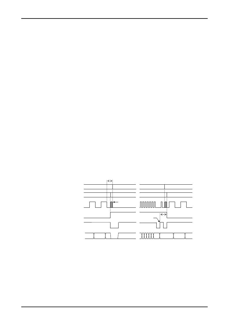
�6.� The� readout� mode� may� be� switched� between� master� and� slave� modes� during� readout.�
�Applications� must� observe� the� following� points� to� assure� data� continuity� during� this� operation.�
�1)� Data� acquisition� timing� in� master� made�
�Data� must� be� read� on� the� falling� edge� of� RDCL�
�2)� Timing� of� the� switch� from� master� mode� to� slave� mode�
�After� the� RDCL� output� goes� low� and� the� RDDA� data� has� been� acquired,� the� application� must� set� MODE�
�high� immediately.�
�Then,� the� microcontroller� starts� output� by� setting� the� RDCL� signal� low.�
�The� microcontroller� RDCL� output� must� start� within� 840� μ� s� (tms)� after� RDCL� went� low.�
�In� this� case,� if� the� last� data� read� in� master� mode� was� data� item� n,� then� data� starting� with� item� n+1�
�will� be� written� to� memory.�
�3)� Timing� of� the� switch� from� slave� mode� to� master� mode�
�After� all� data� has� been� read� from� memory� and� READY� has� gone� high,� the� application� must� then� wait�
�until� READY� goes� low� once� again� the� next� time� (timing� A� in� the� figure),� immediately� read� out� one� bit� of�
�data� and� input� the� RDCL� clock.�
�Then,� at� the� point� READY� goes� high,� the� microcontroller� must� terminate� RDCL� output� and� then� set�
�MODE� low.�
�The� application� must� switch� MODE� to� low� within� 840� μ� s� (tms)� after� READY� goes� low� (timing� A� in� the�
�figure).�
�t� ms�
�RDCL� (microcontroller� status)�
�RDCL� (IC� status)�
�RDCL�
�MODE�
�INPUT�
�OUTPUT�
�OUTPUT�
�INPUT�
�undefined�
�Timing� A�
�t� s� m�
�INPUT�
�OUTPUT�
�READY�
�RDDA�
�n-2�
�n-1�
�n�
�n+1�
�m�
�m+1�
�m+2�
�No.A0503-8/9�
�相关PDF资料 |
PDF描述 |
|---|---|
| VPT30-830 | TRANSF 30VCT .83A WORLD CLASS |
| VPT12-2080 | TRANSF 12VCT 2.08A WORLD CLASS |
| TC32L5A32K7680 | OSCILLATOR 32.7680 KHZ 3.3V SMD |
| POE26W3.3VS5-R | TRANSFRMR 160UH 26W 2.6A POE SMD |
| 4112714 | SILVERCAREPLAN-GROUP1-4YR |
相关代理商/技术参数 |
参数描述 |
|---|---|
| LC72725KV-UMTI-TLM-E | 制造商:Sony Semiconductor Solutions Division 功能描述: |
| LC72725M | 制造商:SANYO 制造商全称:Sanyo Semicon Device 功能描述:CMOS LSI |
| LC72725NV | 制造商:SANYO 制造商全称:Sanyo Semicon Device 功能描述:CMOS LSI |
| LC72725NV-TLM-E | 制造商:Sony Semiconductor Solutions Division 功能描述: |
| LC72725V | 制造商:SANYO 制造商全称:Sanyo Semicon Device 功能描述:CMOS LSI |
发布紧急采购,3分钟左右您将得到回复。