- 您现在的位置:买卖IC网 > PDF目录39191 > LC7454M SPECIALTY CONSUMER CIRCUIT, PDSO20 PDF资料下载
参数资料
| 型号: | LC7454M |
| 元件分类: | 消费家电 |
| 英文描述: | SPECIALTY CONSUMER CIRCUIT, PDSO20 |
| 封装: | MFP-20 |
| 文件页数: | 12/16页 |
| 文件大小: | 696K |
| 代理商: | LC7454M |
LC7454A/M
No.6685-5/16
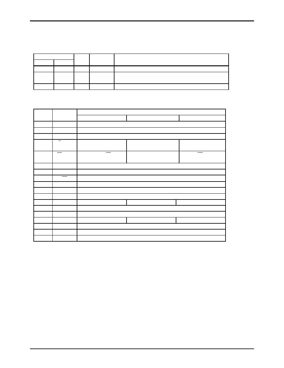
Operation on each mode
The LC7454 has three operating modes. The operation mode be selected by the status of MOD0 and MOD1 terminals. The functionality of
three modes are the same. Only the PLL reference frequency which is used to generate operation clock is different. Use mode1 or mode3
only in the application which uses 2x data. Any mode (Mode1,2 or 3) can be used in the 1x data only application.
Terminal
MOD1
MOD0
MODE
Applications
PLL reference
Open
Mode1
NTSC-VCR
Use H-sync signal which is separated from C-Video signal.
Open
VDD1
Mode2
NTSC-VCR
Use 1/32 divided signal 503 KHz which is generated by external
ceramic resonator.
VDD
Open
Mode3
NTSC-TV
Use H-sync signal from Fly Back.
Terminal Functions
Function Description
Terminal #
(DIP18)
Terminal
name
Mode 1
Mode 2
Mode 3
1
VSS1
Ground
2
TEST
Test terminal, Open in normal operation
3
LN26
32
s Pulse output at line 26 timing on both field
4
O/ E /CFOUT Pulse output for field
judgment
*1
Output terminal for ceramic
resonator
Pulse output for field
judgment
*1
5
HS
/CFIN
Sync separated HS pulse
output
Input terminal for Ceramic
resonator
External HS pulse input
6
DATA
Line select data input and slice data output
*2
7
SCKIN
Data transmit clock input
8
CE
Chip select input
*3
9
IOC
Data direction control signal input
*4
10
SLICE
Pulse output at selected slice line
11
VDD1
Power terminal
12
MOD0
Open
Connect to VDD
Open
13
CVIN
Conposit video input
14
VCOR
Connect resister for internal VCO oscillation frequency control
15
MOD1
Open
Connect to VDD
16
VDD2
Power terminal
17
VSS2
Ground
18
CP
Filter terminal for internal PLL
*1
‘H’ level in Odd field, ‘L’ level in Even field.
*2
N-ch open drain in output mode.
*3
Feed ‘L’ level only when data transmission is in effect. If CE=’H’, data terminal will become
input/output disable, SCKIN terminal will become input disable.
*4
‘H’ level : Output mode
‘L’ level : Input mode
相关PDF资料 |
PDF描述 |
|---|---|
| LC74798M | ON-SCREEN DISPLAY IC, PDSO30 |
| LC74798 | ON-SCREEN DISPLAY IC, PDIP30 |
| LC7480M | 3-CH 6-BIT FLASH METHOD ADC, PARALLEL ACCESS, PDSO24 |
| LC7480 | 3-CH 6-BIT FLASH METHOD ADC, PARALLEL ACCESS, PDIP24 |
| LC75385NE-R | 2 CHANNEL(S), TONE CONTROL CIRCUIT, PQFP44 |
相关代理商/技术参数 |
参数描述 |
|---|---|
| LC7455 | 制造商:SANYO 制造商全称:Sanyo Semicon Device 功能描述:Closed Caption Signal Extraction IC |
| LC7455A | 制造商:SANYO 制造商全称:Sanyo Semicon Device 功能描述:Closed Caption Signal Extraction IC |
| LC7455M | 制造商:SANYO 制造商全称:Sanyo Semicon Device 功能描述:Closed Caption Signal Extraction IC |
| LC7456A | 制造商:SANYO 制造商全称:Sanyo Semicon Device 功能描述:U.S. Closed Caption Signal Extraction IC |
| LC7458B-04 | 制造商:SANYO 制造商全称:Sanyo Semicon Device 功能描述:Closed-Caption Decoder LSI |
发布紧急采购,3分钟左右您将得到回复。