- 您现在的位置:买卖IC网 > PDF目录30736 > LC7872E SPECIALTY CONSUMER CIRCUIT, PQFP64 PDF资料下载
参数资料
| 型号: | LC7872E |
| 元件分类: | 消费家电 |
| 英文描述: | SPECIALTY CONSUMER CIRCUIT, PQFP64 |
| 封装: | QFP-64 |
| 文件页数: | 6/17页 |
| 文件大小: | 295K |
| 代理商: | LC7872E |
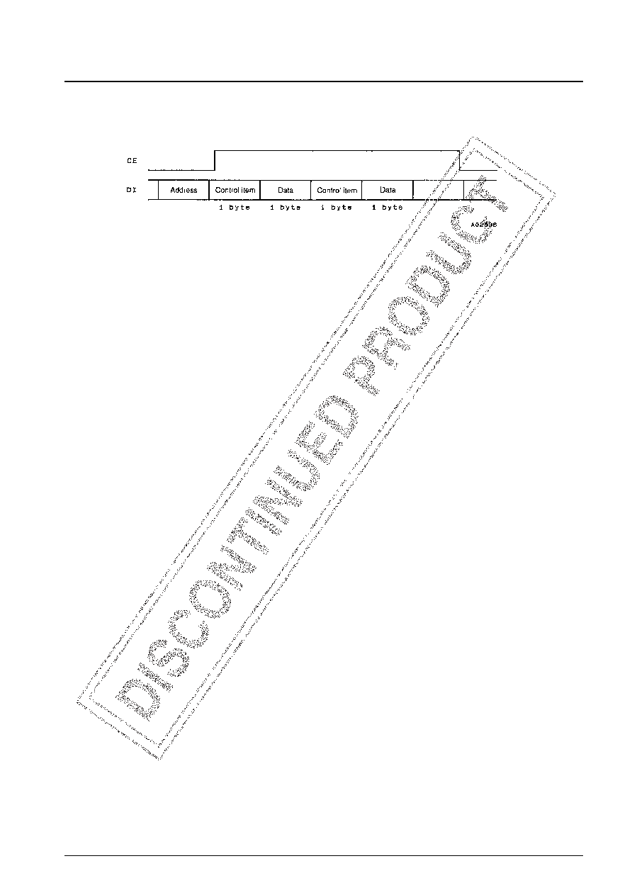
Microcontroller Interface (CCB Bus)
1. 2N byte input command
Address (F4h): lsb
msb
Control item:
lsb
msb; Where AAAA is the register number.
Register 0 (mode setting)
Data: lsb
msb; Default:
A = VRAM/BG
0: Display the contents of VRAM
1: Display the background color (BGC)
B = TV/LINE
0: TV graphics mode
1: Line graphics mode
C = Disk command enable
0: Only disk commands are accepted.
1: Disk commands are ignored and only MGC is accepted.
D = Color bar on/off
0: Off
1: Color bar on
EFG = Comparison conditions in superimposition mode (only valid when SON = 1)
EF = 00: Comparison not performed.
01: When the border color is not black, YS is set high (display) for section whose color does
not match the border color and is set low (clear) otherwise.
11: YS is set high for sections that do not match the chroma key color, and is set low
otherwise.
G = 0: The whole screen is set low (clear) when the comparison condition does not hold for EF
= 00 and EF = 01.
G = 1: The whole screen is set high (display) when the comparison condition does not hold for
EF = 00 and EF = 01.
H = INIT
0: Normal
1: Internal reset
On an internal reset the display screen is set to a blue background screen.
Register 1 (screen position adjustment)
Data: lsb
msb; Default:
H = horizontal direction. The value is specified as a two’s complement value with left being the positive
direction. Position is adjustable in two dot units from –16 to +14 dots from the center.
V = vertical direction. The value is specified as a two’s complement value with up being the positive
direction. Position is adjustable in two dot units from –16 to +14 dots from the center.
Register 2 (on/off settings for channels 0 to 7)
Data: lsb
msb; Default:
C = channel 0 to 7
0: off
1: on
[ 11000000 ]
[CCCCCCCC ]
[ 00000000 ]
[H H HHVVVV ]
[ 00000110 ]
[AB C D E F G H ]
[0 - - - AAAA ]
[0 0 101111 ]
No. 4868-14/17
LC7872E
相关PDF资料 |
PDF描述 |
|---|---|
| LC7874E | SPECIALTY CONSUMER CIRCUIT, PQFP64 |
| LC78835K | SPECIALTY CONSUMER CIRCUIT, PDIP24 |
| LC78835KM | SPECIALTY CONSUMER CIRCUIT, PDSO24 |
| LC78845Q | SPECIALTY CONSUMER CIRCUIT, PQFP48 |
| LC80101M | SPECIALTY CONSUMER CIRCUIT, PDSO28 |
相关代理商/技术参数 |
参数描述 |
|---|---|
| LC7874E | 制造商:SANYO 制造商全称:Sanyo Semicon Device 功能描述:CD Graphics Decorder |
| LC7876E | 制造商:未知厂家 制造商全称:未知厂家 功能描述: |
| LC7880 | 制造商:SANYO 制造商全称:Sanyo Semicon Device 功能描述:16 bit D/A CONVERTER |
| LC7880M | 制造商:SANYO 制造商全称:Sanyo Semicon Device 功能描述:16 bit D/A CONVERTER |
| LC7881 | 制造商:SANYO 制造商全称:Sanyo Semicon Device 功能描述:CMOS LSI |
发布紧急采购,3分钟左右您将得到回复。