- 您现在的位置:买卖IC网 > PDF目录30737 > LC8905V SPECIALTY CONSUMER CIRCUIT, PDSO24 PDF资料下载
参数资料
| 型号: | LC8905V |
| 元件分类: | 消费家电 |
| 英文描述: | SPECIALTY CONSUMER CIRCUIT, PDSO24 |
| 封装: | SSOP-24 |
| 文件页数: | 5/16页 |
| 文件大小: | 223K |
| 代理商: | LC8905V |
3. The following output settings can be controlled:
Channel status (C bit) output
Subcode Q data output
Status ID and shortening ID detection for DAT that use subcodes
C bit output
This function presumes that this IC will be used in consumer mode and thus only handles the first 32 bits.
The flag is fixed at the high level (although there is no flag in the type 1 microprocessor interface timing), and the
data format is LSB first.
Error and update checking is not applied to the data.
The internal shift register is reset if a PLL lock error occurs.
An interval of at least 6 msec must be provided between consecutive data readout operations.
Subcode Q output
Subcode Q can be read out after the fall of the DQSY/LD signal. Also note that the data is updated every time this
signal falls. However, this signal will not be output (fall) unless 96 bits of subcode Q data (include the CRC check
bits) is input.
The flag outputs a high when the CRC check passes, and low if the CRC check fails.
The bit order is LSB first within each byte of the 80 bits of subcode Q data.
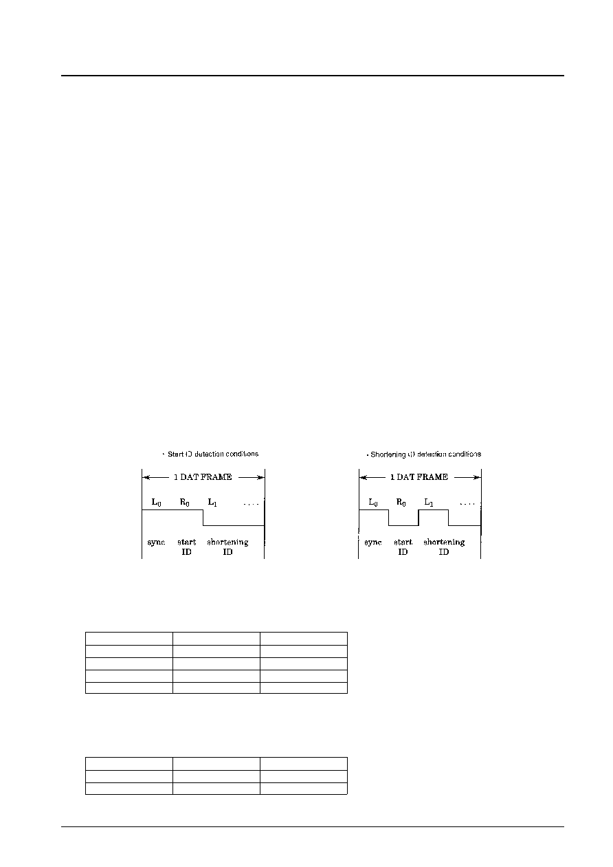
ID detection
The start ID and shortening ID are only detected when the DAT category code (1100000L) is received.
These IDs are detected as follows:
— A low pulse is output from DQSY/LD if a start ID (R0) or a shortening ID (L1) is detected following a sync
signal (L0).
— After this signal, data can be read out from SRDT/DO by inputting the same address value as that used for
subcode Q data to SWDT/DI.
Figure 4 User Data for DAT that Use Subcodes
The table below shows the relationship between the sync signal (L0), the start ID (R0), the shortening ID (L1), and
the data output.
Output pins
The output scheme used for SRDT/DO differs depending on the microprocessor interface format selected by
CKSEL.
No. 5237-13/16
LC8905V
(L0): SYNC
H
(R0): Start ID
H
L
(L1): Shortening ID
L
H
Flags + 80 data bits
all H
all L
Detected ID
Start ID
Shortening ID
CKSEL
Format
SRDT/DO
L
Figure 2
Open-drain output
H
Figure 3
Three-state output
相关PDF资料 |
PDF描述 |
|---|---|
| LC8910 | TRANSMITTER/RECEIVER IC, PDIP24 |
| LC8913 | TRANSMITTER/RECEIVER IC, PDIP40 |
| LC8912 | TRANSMITTER/RECEIVER IC, PDIP28 |
| LC895124 | SPECIALTY CONSUMER CIRCUIT, PQFP144 |
| LC895125Q | SPECIALTY CONSUMER CIRCUIT, PQFP128 |
相关代理商/技术参数 |
参数描述 |
|---|---|
| LC89060 | 制造商:SANYO 制造商全称:Sanyo Semicon Device 功能描述:6-Bit Video D/A Converters |
| LC89060M | 制造商:SANYO 制造商全称:Sanyo Semicon Device 功能描述:6-Bit Video D/A Converters |
| LC89066 | 制造商:SANYO 制造商全称:Sanyo Semicon Device 功能描述:6-Bit Video A/D Converters |
| LC89066M | 制造商:SANYO 制造商全称:Sanyo Semicon Device 功能描述:6-Bit Video A/D Converters |
| LC89075WA-H | 功能描述:音频发送器、接收器、收发器 AUDIO I/F RECEIVER + ADC RoHS:否 制造商:Cirrus Logic 工作电源电压:3.3 V, 5 V 电源电流:11.8 mA 通道数量:1 最大工作温度:+ 70 C 接口类型:I2C, SPI 安装风格:SMD/SMT 封装 / 箱体:TSSOP-28 封装: |
发布紧急采购,3分钟左右您将得到回复。