- 您现在的位置:买卖IC网 > PDF目录30738 > LC898023 SPECIALTY CONSUMER CIRCUIT, PQFP208 PDF资料下载
参数资料
| 型号: | LC898023 |
| 元件分类: | 消费家电 |
| 英文描述: | SPECIALTY CONSUMER CIRCUIT, PQFP208 |
| 封装: | SQFP-208 |
| 文件页数: | 9/12页 |
| 文件大小: | 68K |
| 代理商: | LC898023 |
No. 6494-6/12
LC898023
Continued from preceding page.
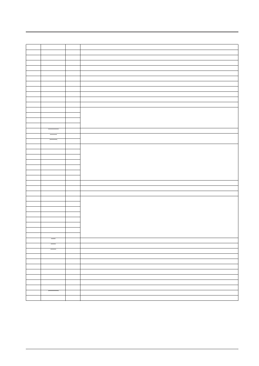
Pin No.
Pin name
Type
Pin function
43
LDH
O
Recording laser diode control signal output
44
VDD
P
Digital system power supply (3.3 V)
45
VSS
P
Digital system ground (VSS)
46
ATEST3
O
Analog block test output
47
ATEST1
O
Analog block test output
48
WDAT
O
Recording laser diode control signal output
49
NWDAT
O
Recording laser diode control signal output (WDAT inverted)
50
VDD
P
Analog system power supply (3.3 V)
51
VSS
P
Analog system ground (VSS)
52
VDD
P
Digital system power supply (5 V)
53
VSS
P
Digital system ground (VSS)
54
R1
I
55
VCNT1
I
Write strategy analog signals
56
MDC1
I
57
PD1
O
58
SWAIT
O
Wait signal to the microcontroller
59
INT0
O
Interrupt request signal outputs to the microcontroller
60
INT1
O
These are open-drain outputs with built-in pull-up resistors.
61
D0
B
62
D1
B
63
D2
B
Microcontroller data signal lines
64
D3
B
These pins have built-in pull-up resistors.
65
D4
B
66
D5
B
67
D6
B
68
VDD
P
Digital system power supply (5 V)
69
VSS
P
Digital system ground (VSS)
70
D7
B
Microcontroller data signal line
71
SUA0
I
72
SUA1
I
73
SUA2
I
74
SUA3
I
Command register selection address
75
SUA4
I
76
SUA5
I
77
SUA6
I
78
SUA7
I
79
CS
I
Chip select signal input from the microcontroller
80
RD
I
Data read signal from the microcontroller
81
WR
I
Data write signal from the microcontroller
82
TEST0
I
Test pin. This pin must be tied to VSS.
83
VCNT
I
VCO control voltage
84
R
I
VCO bias resistor connection
85
PD
O
Charge pump output
86
VDD
P
Analog system power supply (3.3 V)
87
VSS
P
Analog system ground (VSS)
88
TEST1
I
Test pin. This pin must be tied to VSS.
89
RESET
I
Reset input
90
XTALCK0
I
Crystal oscillator circuit input (33.8688 MHz)
Continued on next page.
相关PDF资料 |
PDF描述 |
|---|---|
| LC898093KW | SPECIALTY CONSUMER CIRCUIT, PQFP208 |
| LC898093KL | SPECIALTY CONSUMER CIRCUIT, PQFP208 |
| LC89915 | SPECIALTY CONSUMER CIRCUIT, PDIP8 |
| LC89915M | SPECIALTY CONSUMER CIRCUIT, PDSO8 |
| LC8991 | SPECIALTY CONSUMER CIRCUIT, PDIP8 |
相关代理商/技术参数 |
参数描述 |
|---|---|
| LC898023K | 制造商:未知厂家 制造商全称:未知厂家 功能描述: |
| LC898023KL | 制造商:未知厂家 制造商全称:未知厂家 功能描述: |
| LC898023KW | 制造商:SANYO 制造商全称:Sanyo Semicon Device 功能描述:40ⅴ Playback/16ⅴ Write CD-R/RW Encoder/Decoder IC with Built-in SCSI Interface |
| LC898093 | 制造商:SANYO 制造商全称:Sanyo Semicon Device 功能描述:40ⅴ Playback/12ⅴ Write CD-R/RW Encoder/Decoder IC with Built-in ATAPI Interface |
| LC898093KL | 制造商:未知厂家 制造商全称:未知厂家 功能描述: |
发布紧急采购,3分钟左右您将得到回复。