- 您现在的位置:买卖IC网 > PDF目录30738 > LC89975M SPECIALTY CONSUMER CIRCUIT, PDSO14 PDF资料下载
参数资料
| 型号: | LC89975M |
| 元件分类: | 消费家电 |
| 英文描述: | SPECIALTY CONSUMER CIRCUIT, PDSO14 |
| 封装: | MFP-14 |
| 文件页数: | 5/7页 |
| 文件大小: | 97K |
| 代理商: | LC89975M |
Test Conditions
1. Power-supply current with no input signal applied
2. Pin output voltage with no input signal applied (center bias voltage)
3. Measure the C-OUT output when 350-mVp-p sine wave signals are input to C-IN1 and C-IN2.
GVC = 20 log
[dB]
Measured frequencies
GVC-1
4.429662 MHz
(PAL/GBI)
GVC-2
4.425694 MHz
(4.43 NTSC)
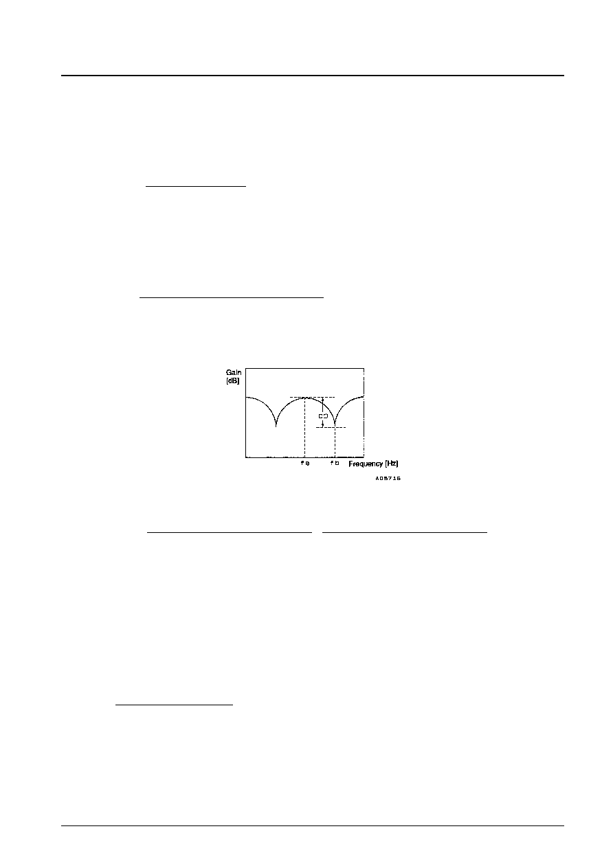
4. Measure the comb depth from the C-OUT output when 350-mVp-p sine wave signals of frequency fa are input to C-
IN1 and C-IN2 and when signals of frequency fb are input.
CD = 20 log
[dB]
Measured frequencies
fa
fb
CD-1
4.429662 MHz
4.425756 MHz
(PAL/GBI)
CD-2
4.425694 MHz
4.417819 MHz
(4.43 NTSC)
5. Measure the C-OUT output when 200-mVp-p sine wave signals are input to C-IN1 and C-IN2 and when 500-mVp-p
sine wave signals are input and calculate the gain difference.
LNC = 20 log (
/
) [dB]
Measured frequencies
LNC-1
4.429662 MHz
(PAL/GBI)
LNC-2
4.425694 MHz
(4.43 NTSC)
6. Measure the 3fsc (13.3 MHz) and fsc (4.43 MHz) components in the C-OUT output with no input signal applied.
7. Measure the noise in the C-OUT output with no input signal applied.
Set up the noise meter with a 200-kHz high-pass filter and a 5-MHz low-pass filter.
8. Let V1 be the C-OUT output when 350-mVp-p sine wave signals are input to C-IN1 and C-IN2 with SW3 in the a
position, and V2 be the C-OUT output with SW3 in the b position.
ZOC =
× 500 []
Measured frequencies
ZOC-1
4.429662 MHz
(PAL/GBI)
ZOC-2
4.425694 MHz
(4.43 NTSC)
V2 [mVp-p] – V1 [mVp-p]
V1 [mVp-p]
Output for a 200-mVp-p input [mVp-p]
200 [mVp-p]
Output for a 500-mVp-p input [mVp-p]
500 [mVp-p]
The C-OUT output for an fb input [mVp-p]
The C-OUT output for an fa input [mVp-p]
C-OUT output [mVp-p]
350 [mVp-p]
No. 5391-5/7
LC89975M
相关PDF资料 |
PDF描述 |
|---|---|
| LC89976 | SPECIALTY CONSUMER CIRCUIT, PDIP14 |
| LC89976M | SPECIALTY CONSUMER CIRCUIT, PDSO14 |
| LC89970-SK | SPECIALTY CONSUMER CIRCUIT, PDIP22 |
| LC89970M-SK | SPECIALTY CONSUMER CIRCUIT, PDSO24 |
| LC89975 | SPECIALTY CONSUMER CIRCUIT, PDIP14 |
相关代理商/技术参数 |
参数描述 |
|---|---|
| LC89977M | 制造商:SANYO 制造商全称:Sanyo Semicon Device 功能描述:CCD Delay Line for PAL |
| LC89978M | 制造商:SANYO 制造商全称:Sanyo Semicon Device 功能描述:CCD Delay Line for Multi-System |
| LC8A008C5477 | 制造商:Panasonic Industrial Company 功能描述:IC |
| LC8-B3H1P-M | 制造商:SMC Corporation of America 功能描述:Controller, AC Servo (master) |
| LC-9 | 功能描述:打印机 LS3E, Component Label, Adhesive Vinyl Cl RoHS:否 制造商:Seiko Instruments 产品:Printer 电源电压: 每行点数:9 x 320 打印速度:52.5 cps, 80 cps 纸张宽度:112 mm |
发布紧急采购,3分钟左右您将得到回复。