- 您现在的位置:买卖IC网 > PDF目录39228 > LFCN-3800 (MINI-CIRCUITS) 7 SECTIONS - 7 SECTIONS, 4850 MHz, CERAMIC LPF PDF资料下载
参数资料
| 型号: | LFCN-3800 |
| 厂商: | MINI-CIRCUITS |
| 英文描述: | 7 SECTIONS - 7 SECTIONS, 4850 MHz, CERAMIC LPF |
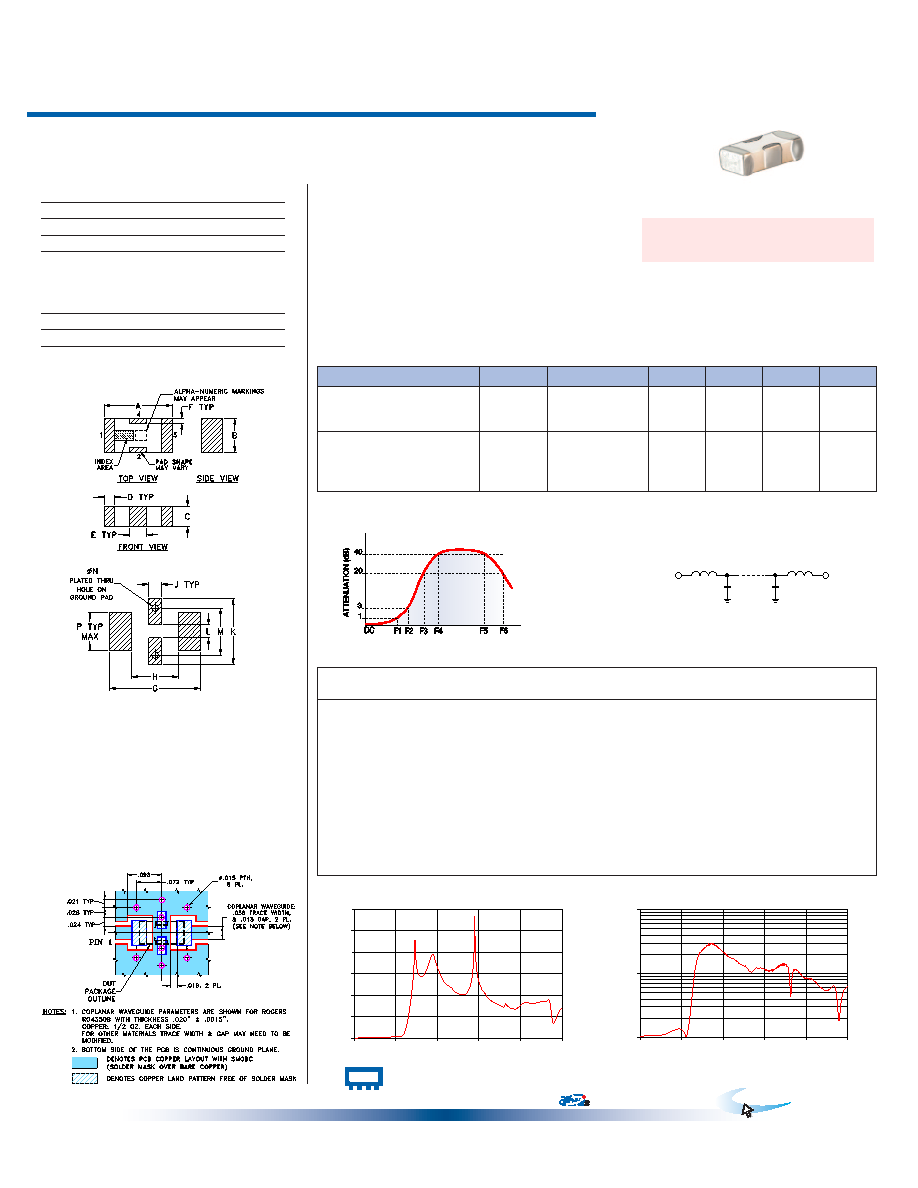
| 封装: | HERMETIC SEALED, CERAMIC,CASE FV1206, 4 PIN |
| 文件页数: | 1/1页 |
| 文件大小: | 406K |
| 代理商: | LFCN-3800 |
Parameter
F#
Frequency (MHz)
Min.
Typ.
Max.
Unit
Pass Band
Insertion Loss
DC-F1
DC-3900
—
1.5
dB
Freq. Cut-Off
F2
4850
—
3.0
—
dB
VSWR
DC-F1
DC-3900
—
1.3
—
:1
Stop Band
Rejection Loss
F3
6000
20
—
dB
F4-F5
5700-8300
—
30
—
dB
F5-F6
8300-13000
—
20
—
dB
VSWR
F3-F6
6000-13000
—
17
—
:1
1. Coupling capacitors at input and output are recommended for use in applications that require DC isolation of input to output port or either port to ground.
Alternatively, if DC pass IN - OUT is required, use the “D” version of this model which will support DC IN-OUT, and provide >100 MOhm isolation to ground.
ISO 9001 ISO 14001 AS 9100 CERTIFIED
Mini-Circuits
P.O. Box 350166, Brooklyn, New York 11235-0003 (718) 934-4500 Fax (718) 332-4661 The Design Engineers Search Engine
Provides ACTUAL Data Instantly at
Notes: 1. Performance and quality attributes and conditions not expressly stated in this specification sheet are intended to be excluded and do not form a part of this specification sheet. 2. Electrical specifications
and performance data contained herein are based on Mini-Circuit’s applicable established test performance criteria and measurement instructions. 3. The parts covered by this specification sheet are subject to
Mini-Circuits standard limited warranty and terms and conditions (collectively, “Standard Terms”); Purchasers of this part are entitled to the rights and benefits contained therein. For a full statement of the Standard
Terms and the exclusive rights and remedies thereunder, please visit Mini-Circuits’ website at www.minicircuits.com/MCLStore/terms.jsp.
For detailed performance specs
& shopping online see web site
minicircuits.com
IF/RF MICROWAVE COMPONENTS
50
DC to 3900 MHz
Low Pass Filter
LFCN-3800+
LFCN-3800
REV. C
M125148
LFCN-3800
EDR-7684/1A
RAV
110414
Page 1 of 1
Ceramic
Frequency
Insertion Loss
VSWR
(MHz)
(dB)
(:1)
40
0.06
1.03
1550
0.27
1.07
3060
0.48
1.25
3900
0.66
1.34
4510
0.95
1.11
4760
1.93
1.95
4850
2.76
2.60
4930
3.84
3.48
5120
7.65
7.05
5380
15.30
14.15
5700
30.21
20.22
6000
33.71
23.49
8300
29.24
19.76
13000
18.04
12.09
20000
14.19
6.35
+ RoHS compliant in accordance
with EU Directive (2002/95/EC)
CASE STYLE: FV1206
PRICE: $2.99 ea. QTY (20)
* Passband rating, derate linearly to 3W at 100°C ambient.
Permanent damage may occur if any of these limits are exceeded.
Operating Temperature
-55°C to 100°C
Storage Temperature
-55°C to 100°C
RF Power Input*
8W max. at 25°C
DC Current Input to Output
0.5A max. at 25°C
The + sufx identies RoHS Compliance. See our web site
for RoHS Compliance methodologies and qualications.
Electrical Specifications at 25°C
Features
excellent power handling, 8W
small size
7 sections
temperature stable
hermetically sealed
LTCC construction
protected by U.S. Patent 6,943,646
Applications
harmonic rejection
VHF/UHF transmitters/receivers
lab use
LFCN-3800
INSERTION LOSS
0
10
20
30
40
50
60
0
4000
8000
12000
16000
20000
FREQUENCY (MHz)
INSERTION
LOSS
(dB)
LFCN-3800
VSWR
1
10
100
0
4000
8000
12000
16000
20000
FREQUENCY (MHz)
VSWR
Typical Performance Data at 25°C
Maximum Ratings
Electrical Schematic
20
3
40
ATTENUATION
(dB)
1
F2 F3
F1
DC
F4
F5
F6
FREQUENCY
R F IN
R F OUT
Typical Frequency Response
RF IN
1
RF OUT
3
GROUND
2,4
Pin Connections
A
B
C
D
E
F
G
.126
.063
.037
.020
.032
.009
.169
3.20
1.60
0.94
0.51
0.81
0.23
4.29
H
J
K
L
M
N
P
wt
.087
.024
.122
.024
.087
.012
.071 grams
2.21
0.61
3.10
0.61
2.21
0.30
1.80
.020
Outline Dimensions (
)
inch
mm
Demo Board MCL P/N: TB-270
Suggested PCB Layout (PL-137)
Outline Drawing
PCB Land Pattern
Suggested Layout,
Tolerance to be within ±.002
相关PDF资料 |
PDF描述 |
|---|---|
| LFCN-3800D+ | 7 SECTIONS - 7 SECTIONS, 4850 MHz, CERAMIC LPF |
| LFCN-3800D | 7 SECTIONS - 7 SECTIONS, 4850 MHz, CERAMIC LPF |
| LFCN-400D+ | 7 SECTIONS - 7 SECTIONS, 560 MHz, CERAMIC LPF |
| LFCN-400D | 7 SECTIONS - 7 SECTIONS, 560 MHz, CERAMIC LPF |
| LFCN-400TR5K+ | 7 SECTIONS - 7 SECTIONS, 560 MHz, LOW PASS FILTER |
相关代理商/技术参数 |
参数描述 |
|---|---|
| LFCN-3800+ | 制造商:Mini-Circuits 功能描述:Filter,LoPass,SM, (T/R) |
| LFCN-400 | 制造商:未知厂家 制造商全称:未知厂家 功能描述:DC to 400 MHz |
| LFCN-4400+ | 制造商:Mini-Circuits 功能描述:7 SECTIONS - 7 SECTIONS, 5290 MHz, CERAMIC LPF |
| LFCN-490 | 制造商:MINI 制造商全称:Mini-Circuits 功能描述:Ceramic Low Pass Filter |
| LFCN-490D | 制造商:MINI 制造商全称:Mini-Circuits 功能描述:Ceramic Low Pass Filter |
发布紧急采购,3分钟左右您将得到回复。