- 您现在的位置:买卖IC网 > PDF目录16471 > LK21252R2K-T (Taiyo Yuden)INDUCTOR MULTILAYER 2.2UH 0805 PDF资料下载
参数资料
| 型号: | LK21252R2K-T |
| 厂商: | Taiyo Yuden |
| 文件页数: | 28/30页 |
| 文件大小: | 0K |
| 描述: | INDUCTOR MULTILAYER 2.2UH 0805 |
| 产品培训模块: | EMC Applications |
| 标准包装: | 4,000 |
| 系列: | LK |
| 电感: | 2.2µH |
| 电流: | 30mA |
| 容差: | ±10% |
| 屏蔽: | 屏蔽 |
| DC 电阻(DCR): | 最大 650 毫欧 |
| Q因子@频率: | 45 @ 100MHz |
| 频率 - 自谐振: | 50MHz |
| 封装/外壳: | 0805(2125 公制) |
| 安装类型: | 表面贴装 |
| 包装: | 带卷 (TR) |
| 工作温度: | -40°C ~ 85°C |
| 频率 - 测试: | 10MHz |
第1页第2页第3页第4页第5页第6页第7页第8页第9页第10页第11页第12页第13页第14页第15页第16页第17页第18页第19页第20页第21页第22页第23页第24页第25页第26页第27页当前第28页第29页第30页
�� �
�
�3.� Considerations� for� automatic� placement�
�◆Adjustment� of� mounting� machine�
�1.� Excessive� impact� load� should� not� be� imposed� on� the� inductors� when� mounting� onto� the� PC� boards.�
�2.� The� maintenance� and� inspection� of� the� mounter� should� be� conducted� periodically.�
�Precautions�
�◆Selection� of� Adhesives�
�1.� Mounting� inductors� with� adhesives� in� preliminary� assembly,� before� the� soldering� stage,� may� lead� to� degraded� inductor� characteristics�
�unless� the� following� factors� are� appropriately� checked;� the� size� of� land� patterns,� type� of� adhesive,� amount� applied,� hardening�
�temperature� and� hardening� period.� Therefore,� it� is� imperative� to� consult� the� manufacturer� of� the� adhesives� on� proper� usage� and�
�amounts� of� adhesive� to� use.�
�◆Adjustment� of� mounting� machine�
�1.� If� the� lower� limit� of� the� pick-up� nozzle� is� low,� too� much� force� may� be� imposed� on� the� inductors,� causing� damage.� To� avoid� this,� the�
�following� points� should� be� considered� before� lowering� the� pick-up� nozzle:�
�(1)� The� lower� limit� of� the� pick-up� nozzle� should� be� adjusted� to� the� surface� level� of� the� PC� board� after� correcting� for� deflection� of� the�
�board.�
�(2)� The� pick-up� pressure� should� be� adjusted� between� 1� and� 3N� static� loads.�
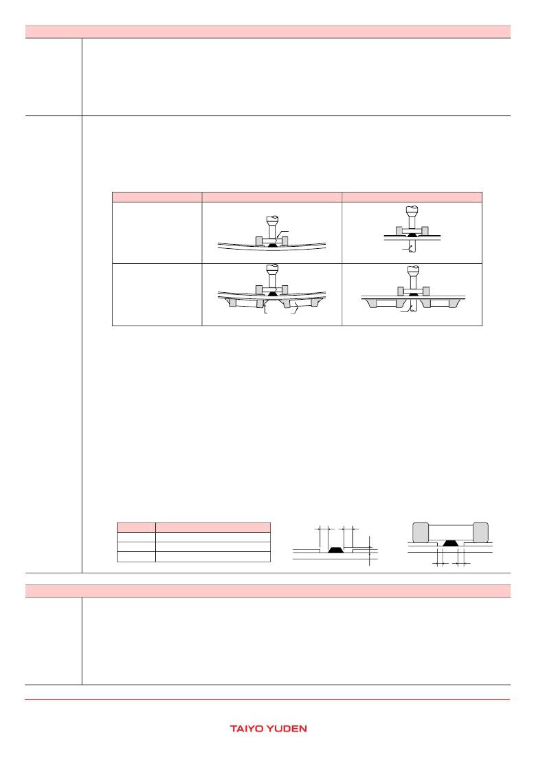
�(3)� To� reduce� the� amount� of� deflection� of� the� board� caused� by� impact� of� the� pick-up� nozzle,� supporting� pins� or� back-up� pins� should� be�
�used� under� the� PC� board.� The� following� diagrams� show� some� typical� examples� of� good� pick-up� nozzle� placement:�
�Item�
�Single-sided� mounting�
�Improper� method�
�chipping�
�or� cracking�
�Proper� method�
�supporting� pins�
�or� back-up� pins�
�Double-sided� mounting�
�chipping�
�or� cracking�
�supporting� pins�
�or� back-up� pins�
�Technical�
�considerations�
�2.� As� the� alignment� pin� wears� out,� adjustment� of� the� nozzle� height� can� cause� chipping� or� cracking� of� the� inductors� because� of� mechanical�
�impact� on� the� inductors.� To� avoid� this,� the� monitoring� of� the� width� between� the� alignment� pin� in� the� stopped� position,� and� maintenance,�
�inspection� and� replacement� of� the� pin� should� be� conducted� periodically.�
�◆Selection� of� Adhesives�
�1.� Some� adhesives� may� cause� reduced� insulation� resistance.� The� difference� between� the� shrinkage� percentage� of� the� adhesive� and� that� of�
�the� inductors� may� result� in� stresses� on� the� inductors� and� lead� to� cracking.� Moreover,� too� little� or� too� much� adhesive� applied� to� the�
�board� may� adversely� affect� component� placement,� so� the� following� precautions� should� be� noted� in� the� application� of� adhesives.�
�(1)� Required� adhesive� characteristics�
�a.� The� adhesive� should� be� strong� enough� to� hold� parts� on� the� board� during� the� mounting� &� solder� process.�
�b.� The� adhesive� should� have� sufficient� strength� at� high� temperatures.�
�c.� The� adhesive� should� have� good� coating� and� thickness� consistency.�
�d.� The� adhesive� should� be� used� during� its� prescribed� shelf� life.�
�e.� The� adhesive� should� harden� rapidly.�
�f.� The� adhesive� must� not� be� contaminated.�
�g.� The� adhesive� should� have� excellent� insulation� characteristics.�
�h.� The� adhesive� should� not� be� toxic� and� have� no� emission� of� toxic� gasses.�
�(2)� When� using� adhesives� to� mount� inductors� on� a� PCB,� inappropriate� amounts� of� adhesive� on� the� board� may� adversely� affect�
�component� placement.� Too� little� adhesive� may� cause� the� inductors� to� fall� off� the� board� during� the� solder� process.� Too� much�
�adhesive� may� cause� defective� soldering� due� excessive� flow� of� adhesive� on� to� the� land� or� solder� pad.�
�[Recommended� conditions]�
�Amount� of� adhesives�
�After� inductors� are� bonded�
�Figure�
�0805� case� sizes� as� examples�
�a� a�
�a� 0.3mm� min�
�b� 100~120μm�
�c� Area� with� no� adhesive�
�b�
�c�
�c�
�4.� Soldering�
�◆Selection� of� Flux�
�1.� Since� flux� may� have� a� significant� effect� on� the� performance� of� inductors,� it� is� necessary� to� verify� the� following� conditions� prior� to� use;�
�(1)� Flux� used� should� be� with� less� than� or� equal� to� 0.1� wt%� (Chlorine� conversion� method)� of� halogenated� content.� Flux� having� a� strong�
�acidity� content� should� not� be� applied.�
�Precautions�
�(2)� When� soldering� inductors� on� the� board,� the� amount� of� flux� applied� should� be� controlled� at� the� optimum� level.�
�(3)� When� using� water-soluble� flux,� special� care� should� be� taken� to� properly� clean� the� boards.�
�◆Soldering�
�1.� Temperature,� time,� amount� of� solder,� etc.� are� specified� in� accordance� with� the� following� recommended� conditions,� and� please� contact� us�
�about� peak� temperature� when� you� use� lead-free� paste.�
�?� This� catalog� contains� the� typical� specification� only� due� to� the� limitation� of� space.� When� you� consider� the� purchase� of� our� products,� please� check� our� specification.�
�For� details� of� each� product� (characteristics� graph,� reliability� information,� precautions� for� use,� and� so� on),� see� our� Web� site� (http://www.ty-top.com/)� .�
�i_mlci_prec_e-E02R01�
�相关PDF资料 |
PDF描述 |
|---|---|
| A3CCB-3018M | IDC CABLE- AKC30B/AE30M/AKC30B |
| VE-JTT-EX | CONVERTER MOD DC/DC 6.5V 75W |
| V48C3V3C75BL2 | CONVERTER MOD DC/DC 3.3V 75W |
| GBA32DRSH-S288 | CONN EDGECARD 64POS .125 EXTEND |
| 6278878-5 | C/A 50/125UM RIS MTRJ 5M1 |
相关代理商/技术参数 |
参数描述 |
|---|---|
| LK21252R2M-T | 功能描述:固定电感器 INDCTR STD MULTILYR 0805 2.2uH 20% RoHS:否 制造商:AVX 电感:10 uH 容差:20 % 最大直流电流:1 A 最大直流电阻:0.075 Ohms 工作温度范围:- 40 C to + 85 C 自谐振频率:38 MHz Q 最小值:40 尺寸:4.45 mm W x 6.6 mm L x 2.92 mm H 屏蔽:Shielded 端接类型:SMD/SMT 封装 / 箱体:6.6 mm x 4.45 mm |
| LK21252R7K-T | 功能描述:固定电感器 INDCTR STD MULTILYR 0805 2.7uH 10% RoHS:否 制造商:AVX 电感:10 uH 容差:20 % 最大直流电流:1 A 最大直流电阻:0.075 Ohms 工作温度范围:- 40 C to + 85 C 自谐振频率:38 MHz Q 最小值:40 尺寸:4.45 mm W x 6.6 mm L x 2.92 mm H 屏蔽:Shielded 端接类型:SMD/SMT 封装 / 箱体:6.6 mm x 4.45 mm |
| LK21252R7M-T | 功能描述:固定电感器 INDCTR STD MULTILYR 0805 2.7uH 20% RoHS:否 制造商:AVX 电感:10 uH 容差:20 % 最大直流电流:1 A 最大直流电阻:0.075 Ohms 工作温度范围:- 40 C to + 85 C 自谐振频率:38 MHz Q 最小值:40 尺寸:4.45 mm W x 6.6 mm L x 2.92 mm H 屏蔽:Shielded 端接类型:SMD/SMT 封装 / 箱体:6.6 mm x 4.45 mm |
| LK2125330K-T | 功能描述:固定电感器 INDCTR STD MULTILYR 0805 33uH 10% RoHS:否 制造商:AVX 电感:10 uH 容差:20 % 最大直流电流:1 A 最大直流电阻:0.075 Ohms 工作温度范围:- 40 C to + 85 C 自谐振频率:38 MHz Q 最小值:40 尺寸:4.45 mm W x 6.6 mm L x 2.92 mm H 屏蔽:Shielded 端接类型:SMD/SMT 封装 / 箱体:6.6 mm x 4.45 mm |
| LK2125330M-T | 功能描述:固定电感器 INDCTR STD MULTILYR 0805 33uH 20% RoHS:否 制造商:AVX 电感:10 uH 容差:20 % 最大直流电流:1 A 最大直流电阻:0.075 Ohms 工作温度范围:- 40 C to + 85 C 自谐振频率:38 MHz Q 最小值:40 尺寸:4.45 mm W x 6.6 mm L x 2.92 mm H 屏蔽:Shielded 端接类型:SMD/SMT 封装 / 箱体:6.6 mm x 4.45 mm |
发布紧急采购,3分钟左右您将得到回复。