- 您现在的位置:买卖IC网 > PDF目录30743 > LM1203CN (TEXAS INSTRUMENTS INC) 3 CHANNEL, VIDEO AMPLIFIER, PDIP28 PDF资料下载
参数资料
| 型号: | LM1203CN |
| 厂商: | TEXAS INSTRUMENTS INC |
| 元件分类: | 音频/视频放大 |
| 英文描述: | 3 CHANNEL, VIDEO AMPLIFIER, PDIP28 |
| 封装: | PLASTIC, DIP-28 |
| 文件页数: | 2/8页 |
| 文件大小: | 188K |
| 代理商: | LM1203CN |
LM1203C
RGB VIDEO-AMPLIFIER SYSTEM
SLVS099B – NOVEMBER 1994 – REVISED FEBRUARY 1996
2
POST OFFICE BOX 655303
DALLAS, TEXAS 75265
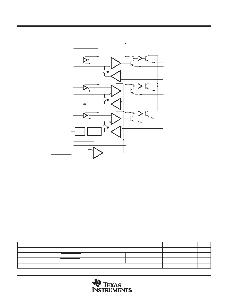
functional block diagram
14
1.4 V
13
CONTRAST
12
REF
11
CAP
B CLAMP 10
2.4 V
Ref
B VIDEO IN
9
CAP
G CLAMP 8
GND
7
G VIDEO IN
6
R CLAMP CAP 5
R VIDEO IN
4
3
CONTRAST CAP2
CONTRAST CAP1
2
1
Control
Contrast
B CLAMP(+)
15
B CLAMP(–)
17
B GAIN ADJUST
18
B VIDEO OUT
16
G CLAMP(+)
19
G CLAMP(–)
21
G GAIN ADJUST
22
G VIDEO OUT
20
23
R CLAMP(+)
24
R CLAMP(–)
26
R GAIN ADJUST
27
R VIDEO OUT
25
VCC1
CLAMP GATE
VCC2
40
1 k
100
VCC1
28
1 k
1 k
100
100
40
40
RED
GREEN
BLUE
absolute maximum ratings over operating free-air temperature range (unless otherwise noted)
Supply voltage, VCC (see Note 1)
13.5 V
. . . . . . . . . . . . . . . . . . . . . . . . . . . . . . . . . . . . . . . . . . . . . . . . . . . . . . . . .
Input voltage range, VI
VCC ≥ VI ≥ GND
. . . . . . . . . . . . . . . . . . . . . . . . . . . . . . . . . . . . . . . . . . . . . . . . . . . . . . . . . . .
Video output current
28 mA
. . . . . . . . . . . . . . . . . . . . . . . . . . . . . . . . . . . . . . . . . . . . . . . . . . . . . . . . . . . . . . . . . . . . . .
Total power dissipation at (or below) 25
°C free-air temperature (see Note 2)
2.5 W
. . . . . . . . . . . . . . . . . . . . .
Operating junction temperature, TJ
150
°C
. . . . . . . . . . . . . . . . . . . . . . . . . . . . . . . . . . . . . . . . . . . . . . . . . . . . . . . . .
Operating free-air temperature range, TA
0
°C to 70°C
. . . . . . . . . . . . . . . . . . . . . . . . . . . . . . . . . . . . . . . . . . . . . .
Storage temperature range, Tstg
–65
°C to 150°C
. . . . . . . . . . . . . . . . . . . . . . . . . . . . . . . . . . . . . . . . . . . . . . . . . .
Lead temperature 1,6 mm (1/16 inch) from case for 10 seconds
260
°C
. . . . . . . . . . . . . . . . . . . . . . . . . . . . . . .
Stresses beyond those listed under “absolute maximum ratings” may cause permanent damage to the device. These are stress ratings only, and
functional operation of the device at these or any other conditions beyond those indicated under “recommended operating conditions” is not
implied. Exposure to absolute-maximum-rated conditions for extended periods may affect device reliability.
NOTES:
1. All VCC terminals must be externally wired together to prevent internal damage during VCC power-on/off cycles.
2. For operation above 25
°C free-air temperature, derate linearly at the rate of 20 mW/°C.
recommended operating conditions
MIN
NOM
MAX
UNIT
Supply voltage, VCC1 and VCC2
12
V
High-level input voltage range, CLAMP GATE, VIH
Clamp comparators off
2
V
Low-level input voltage range, CLAMP GATE, VIL
Clamp comparators on
0.8
V
Operating free-air temperature, TA
0
70
°C
相关PDF资料 |
PDF描述 |
|---|---|
| LM1205AN | 3 CHANNEL, VIDEO AMPLIFIER, PDIP28 |
| LM1207AN | 3 CHANNEL, VIDEO AMPLIFIER, PDIP28 |
| LM1209N | 3 CHANNEL, VIDEO AMPLIFIER, PDIP28 |
| LM1212MX | 1 CHANNEL, VIDEO AMPLIFIER, PDSO20 |
| LM1212M | 1 CHANNEL, VIDEO AMPLIFIER, PDSO20 |
相关代理商/技术参数 |
参数描述 |
|---|---|
| LM1203FN | 制造商:未知厂家 制造商全称:未知厂家 功能描述:Triple Video Amplifier |
| LM1203N | 制造商:NSC 制造商全称:National Semiconductor 功能描述:RGB Video Amplifier System |
| LM1203-N | 制造商:TI 制造商全称:Texas Instruments 功能描述:LM1203 RGB Video Amplifier System |
| LM1204 | 制造商:NSC 制造商全称:National Semiconductor 功能描述:150 MHz RGB Video Amplifier System |
| LM1204V | 制造商:Texas Instruments 功能描述: |
发布紧急采购,3分钟左右您将得到回复。