- 您现在的位置:买卖IC网 > PDF目录30743 > LM1238AAF/NA (NATIONAL SEMICONDUCTOR CORP) 3 CHANNEL, VIDEO PREAMPLIFIER, PDIP24 PDF资料下载
参数资料
| 型号: | LM1238AAF/NA |
| 厂商: | NATIONAL SEMICONDUCTOR CORP |
| 元件分类: | 音频/视频放大 |
| 英文描述: | 3 CHANNEL, VIDEO PREAMPLIFIER, PDIP24 |
| 封装: | N24D |
| 文件页数: | 14/24页 |
| 文件大小: | 1207K |
| 代理商: | LM1238AAF/NA |
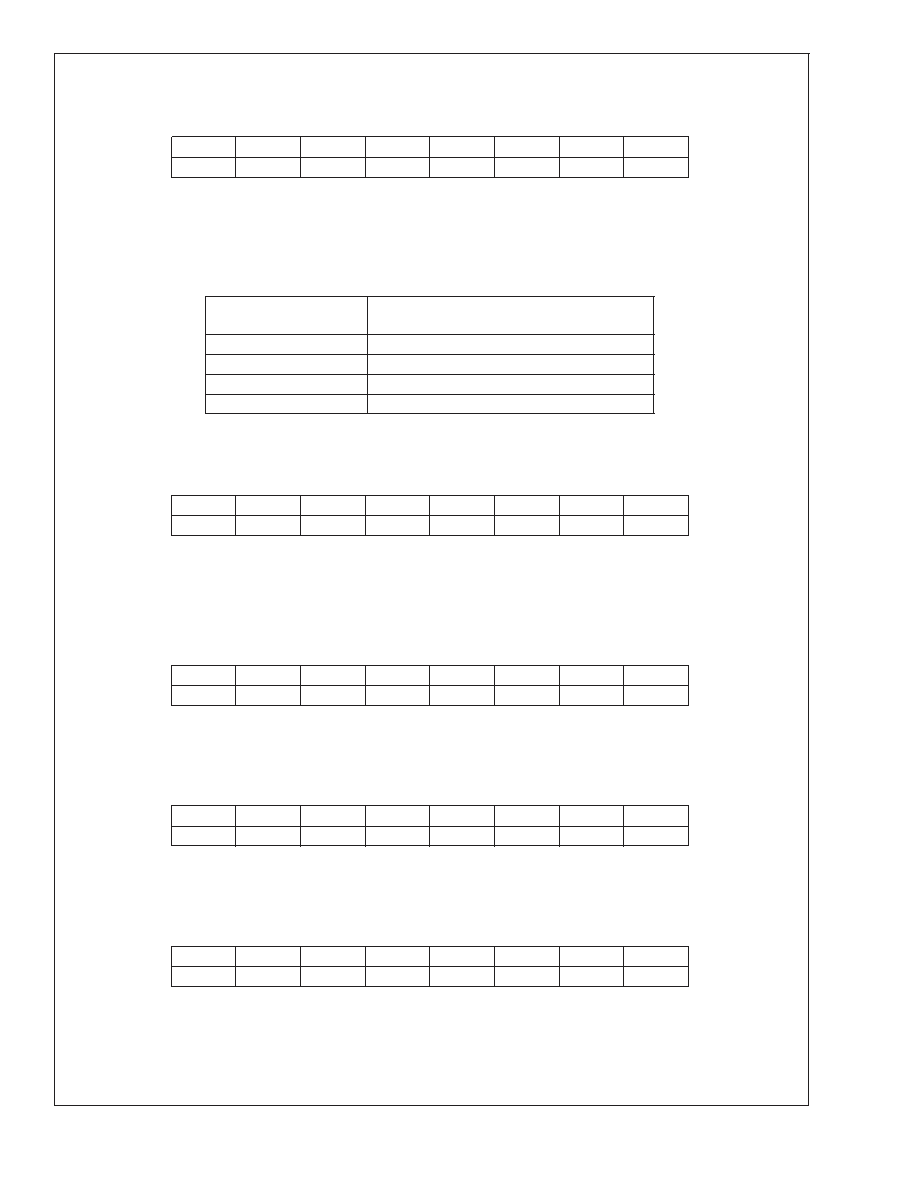
Control Register Definitions (Continued)
Icon Alternate Period Control Register (I
2C address 0x0804h)
Register Name (address): ALT (0x0804h)
7
654321
0
RSV
ASO1
ASO0
ALT3
ALT2
ALT1
ALT0
Bits 3–0 Icon Alternate Period. These four bits set the period at which the icon will switch between images, in increments of eight
vertical fields.
Bits 5–4 Alternate Sequence Override. These two bits enable the automatic alternating sequence of icons, or allow the icon to
be set to one of the three alternative screens.
TABLE 8. Alternating Icon Sequence Override
Sequence Override
Register Value
Effect
00
Automatic Alternating Sequence
01
Set for Icon Screen 0
10
Set for Icon Screen 1
11
Set for Icon Screen 2
Bits 7–6 Reserved.
Vertical Blank Duration Control Register (I
2C address 0x0805h)
Register Name (address): VERTBLNK (0x0805h)
7
654321
0
RSV
VB6
VB5
VB4
VB3
VB2
VB1
VB0
Bits 6–0 Vertical Blank Duration. These seven bits set the duration of the VBLANK signal in numbers of horizontal scans.
Bit 7
Reserved.
PRE-AMPLIFIER INTERFACE REGISTERS
Blue Channel Gain Control Register (I
2C address 0x0810h)
Register Name (address): BGAINCTRL (0x0810h)
7
654321
0
RSV
BG
Bits 6–0 Blue Channel Gain Control. These seven bits determine the gain for the Blue Channel.
Bit 7
Reserved.
Green Channel Gain Control Register (I
2C address 0x0811h)
Register Name (address): GGAINCTRL1 (0x0811h)
7
654321
0
RSV
GG
Bits 6–0 Green Channel Gain Control. These seven bits determine the gain for the Green Channel.
Bit 7
Reserved.
Red Channel Gain Control Register (I
2C address 0x0812h)
Register Name (address): RGAINCTRL1 (0x0812h)
7
654321
0
RSV
RG
Bits 6–0 Red Channel Gain Control. These seven bits determine the gain for the Red Channel.
Bit 7
Reserved.
LM1238
www.national.com
21
相关PDF资料 |
PDF描述 |
|---|---|
| LM1246AAA/NA | 3 CHANNEL, VIDEO PREAMPLIFIER, PDIP24 |
| LM1247AAG/NA/NOPB | 3 CHANNEL, VIDEO PREAMPLIFIER, PDIP24 |
| LM1253AAE/NA | ON-SCREEN DISPLAY IC, PDIP28 |
| LM1267NA/NOPB | 3 CHANNEL, VIDEO PREAMPLIFIER, PDIP24 |
| LM1269NA/NOPB | 3 CHANNEL, VIDEO PREAMPLIFIER, PDIP24 |
相关代理商/技术参数 |
参数描述 |
|---|---|
| LM123AK-05 | 制造商:未知厂家 制造商全称:未知厂家 功能描述:Voltage Regulator |
| LM123AK-05-883B | 制造商:未知厂家 制造商全称:未知厂家 功能描述:Voltage Regulator |
| LM123AK-12 | 制造商:未知厂家 制造商全称:未知厂家 功能描述:Voltage Regulator |
| LM123AK-12-883B | 制造商:未知厂家 制造商全称:未知厂家 功能描述:Voltage Regulator |
| LM123AK-15 | 制造商:未知厂家 制造商全称:未知厂家 功能描述:Voltage Regulator |
发布紧急采购,3分钟左右您将得到回复。