- 您现在的位置:买卖IC网 > PDF目录30743 > LM1279AN/NOPB (NATIONAL SEMICONDUCTOR CORP) 3 CHANNEL, VIDEO AMPLIFIER, PDIP20 PDF资料下载
参数资料
| 型号: | LM1279AN/NOPB |
| 厂商: | NATIONAL SEMICONDUCTOR CORP |
| 元件分类: | 音频/视频放大 |
| 英文描述: | 3 CHANNEL, VIDEO AMPLIFIER, PDIP20 |
| 封装: | DIP-20 |
| 文件页数: | 6/13页 |
| 文件大小: | 511K |
| 代理商: | LM1279AN/NOPB |
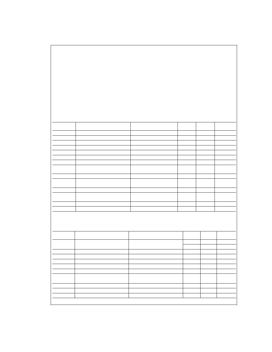
Absolute Maximum Ratings (Note 1)
If Military/Aerospace specified devices are required,
please contact the National Semiconductor Sales Office/
Distributors for availability and specifications.
Supply Voltage
Pins 2 and 16 (Note 3)
10V
Peak Video Output Source Current
(Any One Amp) Pins 13, 15, or 18
28 mA
Voltage at Any Input Pin (V
IN)VCC ≥ VIN ≥ GND
Power Dissipation (P
D)
(Above 25C Derate Based on
θ
JA
and T
J)
2.1W
Thermal Resistance to Ambient (
θ
JA)
60C/W
Thermal Resistance to Case (
θ
JA)
37C/W
Junction Temperature (T
J)
150C
ESD Susceptibility (Note 4)
3.5 kV
ESD Machine Model (Note 16)
300V
Storage Temperature
65C to 150C
Lead Temperature
(Soldering, 10 sec.)
265C
Operating Ratings (Note 2)
Temperature Range
0C to 70C
Supply Voltage (V
CC)
7.5V
≤ V
CC ≤ 8.5V
DC Electrical Characteristics
T
A = 25C; VCC1 =VCC2 = 8V; V10 = 4V; VDrive = 4V; V11 = 7V; VOSD = 0V unless otherwise stated.
Symbol
Parameter
Condition
Typical
(Note 5)
Limit
(Note 6)
Units
I
S
Supply Current
I
CC1 +ICC2 ILoad (Note 7)
80
90
mA(max)
V
3, 5, 8
Video Amplifier Input Bias Voltage
2.5
V
R
IN
Video Input Resistance
Any One Amplifier
20
k
V
11clamp
Clamp Voltage
3.2
3.6
V (min)
I
11 clamp off
Clamp Off Current
V
11 = 0V
5.0
8.0
A(max)
I
11 clamp on
Clamp On Current
V
11 = 6.5V
100
500
nA (max)
I
clamp
Clamp Cap Charge Current
Clamp Comparators On
±750
±500
A(min)
I
bias
Clamp Cap Bias Discharge
Current
Clamp Comparators Off
50
200
nA (max)
V
OL
Video Black Level
V
Video in = 0V, V11 = 6.5V
1.35
1.55
V (max)
V
OL
Video
Black Level Output
Voltage
Between Any Two Amplifiers
±50
±200
mV (max)
V
OH
Video Output High Voltage
V
11 < 1.2V
5.0
4.6
V (min)
I
10, 12, 14, 17
Contrast/Drive Control Input
Current
V
Contrast =VDrive =0Vto4V
0.25
1.5
A (max)
I
1I, 19I, 20I
OSD Low Input Current (each)
V
OSD in = 0V
2.5
10
A(max)
I
1h, 19h, 20h
OSD High Input Current (each)
V
OSD in = 5V
100
130
A (max)
AC Electical Characteristics
T
A = 25C; VCC1 =VCC2 = 8V. Manually adjust Video Output pins 13, 15, and 18 to 4V DC for the AC test unless otherwise
stated. (Note 15)
Symbol
Parameter
Conditions
Typical
(Note 5)
Limit
(Note 6)
Units
A
Vmax
Video Amplifier Gain
V
10 = 4V, VIN = 635 mVPP
6.8
5.9
V/V (min)
V
drive = 4V
16.7
15.4
dB (min)
A
V2V
Contrast Attenuation @ 2V
Ref: A
V max, V10 =2V
6
dB
A
V 0.25V
Contrast Attenuation @ 0V
Ref: A
V max, V10 = 0V
35
dB
Drive
Drive Control Range
V
drive =0Vto4V, V10 =4V
12
dB
A
V match
Absolute Gain Match @ A
V max
V
10 = 4V, Vdrive = 4V (Note 9)
±0.3
dB
A
V track
Gain Change Between Amplifiers
V
10 = 4V to 2V (Notes 9, 10)
±0.3
dB
f(3 dB)
Video Amplifier Bandwidth
V
10 = 4V, Vdrive = 4V,
110
MHz
(Notes 11, 12))
V
O = 3.5 VP-P
t
r(Video)
Video Output Rise Time
V
O = 3.5 VP-P (Note 11)
3.6
ns
t
f(Video)
Video Output Fall Time
V
O = 3.5 VP-P (Note 11)
3.2
ns
V
sep 10 kHz
Video Amplifier 10 kHz Isolation
V
10 = 4V (Note 13)
70
dB
LM1279A
www.national.com
2
相关PDF资料 |
PDF描述 |
|---|---|
| LM1279N/NOPB | 1 CHANNEL, VIDEO AMPLIFIER, PDIP20 |
| LM136A-2.5MD8 | 1-OUTPUT TWO TERM VOLTAGE REFERENCE, 5 V, UUC |
| LM136A-5.0MW8 | 1-OUTPUT TWO TERM VOLTAGE REFERENCE, 5 V, UUC |
| LM136A-5.0MD8 | 1-OUTPUT TWO TERM VOLTAGE REFERENCE, 5 V, UUC |
| LM1496MX | SPECIALTY CONSUMER CIRCUIT, PDSO14 |
相关代理商/技术参数 |
参数描述 |
|---|---|
| LM1279DL WAF | 制造商:Texas Instruments 功能描述: |
| LM1279N | 功能描述:IC VIDEO AMP SYS 110MHZ 20-DIP RoHS:是 类别:集成电路 (IC) >> 线性 - 放大器 - 视频放大器和频缓冲器 系列:- 标准包装:1,000 系列:- 应用:驱动器 输出类型:差分 电路数:3 -3db带宽:350MHz 转换速率:1000 V/µs 电流 - 电源:14.5mA 电流 - 输出 / 通道:60mA 电压 - 电源,单路/双路(±):5 V ~ 12 V,±2.5 V ~ 6 V 安装类型:表面贴装 封装/外壳:20-VFQFN 裸露焊盘 供应商设备封装:20-QFN 裸露焊盘(4x4) 包装:带卷 (TR) |
| LM1281 | 制造商:NSC 制造商全称:National Semiconductor 功能描述:85 MHz RGB Video Amplifier System with On Screen Display (OSD) |
| LM1281CL WAF | 制造商:Texas Instruments 功能描述: |
| LM1281N | 制造商:Rochester Electronics LLC 功能描述:- Bulk 制造商:Panasonic Industrial Company 功能描述:IC |
发布紧急采购,3分钟左右您将得到回复。