- 您现在的位置:买卖IC网 > PDF目录44530 > LM1572MTC-3.3/NOPB (NATIONAL SEMICONDUCTOR CORP) 3.2 A SWITCHING REGULATOR, 570 kHz SWITCHING FREQ-MAX, PDSO16 PDF资料下载
参数资料
| 型号: | LM1572MTC-3.3/NOPB |
| 厂商: | NATIONAL SEMICONDUCTOR CORP |
| 元件分类: | 稳压器 |
| 英文描述: | 3.2 A SWITCHING REGULATOR, 570 kHz SWITCHING FREQ-MAX, PDSO16 |
| 封装: | TSSOP-16 |
| 文件页数: | 3/17页 |
| 文件大小: | 583K |
| 代理商: | LM1572MTC-3.3/NOPB |
Application Information (Continued)
inductor for the application. 10H is a more widely available
standard value, and very close to the optimum value too, and
would therefore be a good choice too. Note that inductances
larger than 15H are not recommended in general.
To more accurately predict how the selected off-the-shelf
part will actually perform in the real application, the designer
is referred to AN-1197. The procedure contained therein
could greatly help in correctly choosing the lowest accept-
able current/energy rating of the inductor, and thereby reduc-
ing its size further.
Input Capacitor Selection
At the input, the first requirement is a high frequency (pref-
erably ceramic) decoupling capacitor, of value 0.1F, placed
very close to, and between the V
IN pins and the Ground Pins
of the IC. This provides the triangular pulsed current wave-
form that flows through the switch. In addition, a bulk capaci-
tor is also required, which replenishes the decoupling ca-
pacitor, and may be placed slightly further away if necessary.
The rating and selection of this capacitor is discussed below.
In general a standard low-esr aluminum electrolytic is rec-
ommended at the input (’esr’ refers to the equivalent series
resistance hereafter). There are several reasons for this.
Firstly, tantalum capacitors have inherent input surge-current
limitations. So when the input surge current comes from a
very low impedance source (such as a high current lab DC
power supply), there is a chance that the capacitor may not
survive several such repeated high dV/dt events. In any
case, even using ’surge-tested’ tantalums (like TPS series
from AVX) a 50% voltage derating is recommended in such
conditions. Therefore hypothetically, a 35V tantalum must be
used for the preceding example, in which the maximum input
was 16V. The second reason for avoiding very low esr input
capacitors is that there is a possibility of severe input oscil-
lations. The elements involved in this resonance are the
inductance of the input leads, the input capacitance and the
(negative) input impedance of the switching stage. It is
known that the esr of the input capacitor actually serves a
useful purpose in damping out these oscillations.
These oscillations can only be seen clearly under lab condi-
tions if the output of the lab DC power supply is ON/Output-
Enabled and then the lead from the converter stage is physi-
cally connected to the output terminals of the DC power
supply. Just turning the DC power supply ON/OFF (or with
an Output-Enable button) does not generate the high dV/dt
required to provoke these oscillations. Under a real situation,
input oscillations can become severe enough to cause the
maximum voltage rating of the IC to be exceeded. The
ringing can in turn, also feed in to the Analog sections of the
LM1572, causing strange behavior and possibly device fail-
ure.
The designer needs to therefore monitor the input ramp
close to the input of the converter, preferably with a digitizing
oscilloscope set to about 10-20s/div and using the single
acquisition mode. Once the ramp is being captured, it will be
seen that large input capacitances ’slow’ the dV/dt consider-
ably, thereby reducing the overshoot and the input oscilla-
tions. However, besides the capacitance itself, the esr of the
input capacitor is a major contributor too. Therefore, in a
typical comparison of a 10F aluminum electrolytic vs. a
10F tantalum electrolytic (tantalum has lower esr), it was
seen that there was an almost 50% overshoot in the peak
input voltage for the tantalum capacitor (accompanied by
severe ringing), whereas for the aluminum capacitor, the
overshoot was only about 10% (plus the waveform was that
of a well damped system). The designer should also be
aware that some older DC power supplies actually exacer-
bate the problem, while apparently trying to ’correct’ the
output voltage. The situation gets even worse if the DC
power supply has a remote-sense which is being used to
apparently ’correct’ the input voltage at the input of the
converter. Therefore, it is always a good idea to try out
another available DC power supply to see how severe the
problem is in reality, or whether it is just a ’bad’ lab supply.
If because of size constraints the designer must use tantal-
ums, a minimum capacitance of 22F is recommended for
any application, irrespective of input/output conditions. This
’softens’ up the input dV/dt significantly and reduces the
ringing.
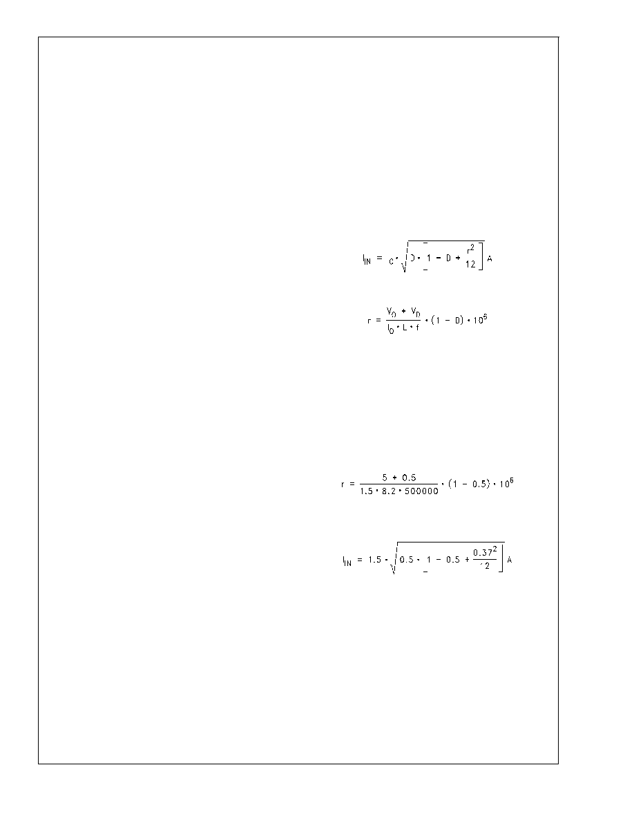
The basic electrical criterion for selecting an input capacitor
is the input RMS current. The equation for this is
where ’r’ is the current ripple ratio. It is given by
where L is in H and f in Hz. This calculation should be done
at the worst case condition for this parameter, which corre-
sponds to 50% duty cycle. If the application never ’sees’ 50%
duty cycle over its entire operating range, then the worst
case is simply the closest duty cycle to 50%. This can, in
general, occur at either of the input voltage extremes, and
therefore both ends must then be examined. In the example,
it was seen that the duty cycle varies from 34.4% to 65%. So
it is clear that there does exist an input voltage point within
the range, at which the duty cycle is 50%. At this worst-case
condition, for the chosen inductor, ’r’ at D=0.5 is
r = 0.45
At this point the input RMS current in the capacitor is
I
IN = 0.76A
Therefore, this is also the minimum required RMS current
rating of any input capacitor to be used. Now, a typical 25V
aluminum capacitor would need to be around 470-1000F
just to be able to handle this current. It would also take up
valuable space on the board. Therefore for the example, the
choice is tantalum 22F/35V TPS series AVX capacitor, Part
Number TPSE226K035S0200, rated for 0.812A at 85C.
Though it is also possible to use a Panasonic surface mount
aluminum
470F/25V
FK
series,
Part
Number
EEVFK1E471P, rated for 0.85A at 105C.
LM1572
www.national.com
11
相关PDF资料 |
PDF描述 |
|---|---|
| LM1572MTC-ADJ/NOPB | 3.2 A SWITCHING REGULATOR, 570 kHz SWITCHING FREQ-MAX, PDSO16 |
| LM1575J-ADJ/883 | 3 A SWITCHING REGULATOR, 58 kHz SWITCHING FREQ-MAX, CDIP16 |
| LM1575J-5.0/883 | 3 A SWITCHING REGULATOR, 58 kHz SWITCHING FREQ-MAX, CDIP16 |
| LM1575J-15/883 | 3 A SWITCHING REGULATOR, 58 kHz SWITCHING FREQ-MAX, CDIP16 |
| LM1575J-12/883 | 3 A SWITCHING REGULATOR, 58 kHz SWITCHING FREQ-MAX, CDIP16 |
相关代理商/技术参数 |
参数描述 |
|---|---|
| LM1572MTC-5.0/NOPB | 功能描述:IC REG BUCK 5V 1.5A 16TSSOP RoHS:是 类别:集成电路 (IC) >> PMIC - 稳压器 - DC DC 开关稳压器 系列:- 产品培训模块:Lead (SnPb) Finish for COTS Obsolescence Mitigation Program 标准包装:1 系列:- 类型:降压(降压) 输出类型:固定 输出数:1 输出电压:3.3V 输入电压:4.5 V ~ 24 V PWM 型:- 频率 - 开关:- 电流 - 输出:125mA 同步整流器:无 工作温度:-40°C ~ 85°C 安装类型:表面贴装 封装/外壳:SOT-23-6 包装:Digi-Reel® 供应商设备封装:SOT-6 其它名称:MAX1836EUT33#TG16DKR |
| LM1572MTC-ADJ | 制造商:Texas Instruments 功能描述:IC V REG BUCK 1.5A ADJ SMD 1572 |
| LM1572MTC-ADJ/NOPB | 功能描述:IC REG BUCK ADJ 1.5A 16TSSOP RoHS:是 类别:集成电路 (IC) >> PMIC - 稳压器 - DC DC 开关稳压器 系列:- 产品培训模块:Lead (SnPb) Finish for COTS Obsolescence Mitigation Program 标准包装:1 系列:- 类型:降压(降压) 输出类型:固定 输出数:1 输出电压:3.3V 输入电压:4.5 V ~ 24 V PWM 型:- 频率 - 开关:- 电流 - 输出:125mA 同步整流器:无 工作温度:-40°C ~ 85°C 安装类型:表面贴装 封装/外壳:SOT-23-6 包装:Digi-Reel® 供应商设备封装:SOT-6 其它名称:MAX1836EUT33#TG16DKR |
| LM1572MTCX-3.3/NOPB | 功能描述:IC REG BUCK 3.3V 1.5A 16TSSOP RoHS:是 类别:集成电路 (IC) >> PMIC - 稳压器 - DC DC 开关稳压器 系列:- 产品培训模块:Lead (SnPb) Finish for COTS Obsolescence Mitigation Program 标准包装:1 系列:- 类型:降压(降压) 输出类型:固定 输出数:1 输出电压:3.3V 输入电压:4.5 V ~ 24 V PWM 型:- 频率 - 开关:- 电流 - 输出:125mA 同步整流器:无 工作温度:-40°C ~ 85°C 安装类型:表面贴装 封装/外壳:SOT-23-6 包装:Digi-Reel® 供应商设备封装:SOT-6 其它名称:MAX1836EUT33#TG16DKR |
| LM1572MTCX-5.0/NOPB | 功能描述:IC REG BUCK 5V 1.5A 16TSSOP RoHS:是 类别:集成电路 (IC) >> PMIC - 稳压器 - DC DC 开关稳压器 系列:- 产品培训模块:Lead (SnPb) Finish for COTS Obsolescence Mitigation Program 标准包装:1 系列:- 类型:降压(降压) 输出类型:固定 输出数:1 输出电压:3.3V 输入电压:4.5 V ~ 24 V PWM 型:- 频率 - 开关:- 电流 - 输出:125mA 同步整流器:无 工作温度:-40°C ~ 85°C 安装类型:表面贴装 封装/外壳:SOT-23-6 包装:Digi-Reel® 供应商设备封装:SOT-6 其它名称:MAX1836EUT33#TG16DKR |
发布紧急采购,3分钟左右您将得到回复。