- 您现在的位置:买卖IC网 > PDF目录30743 > LM1837N (NATIONAL SEMICONDUCTOR CORP) 2 CHANNEL, AUDIO PREAMPLIFIER, PDIP18 PDF资料下载
参数资料
| 型号: | LM1837N |
| 厂商: | NATIONAL SEMICONDUCTOR CORP |
| 元件分类: | 音频/视频放大 |
| 英文描述: | 2 CHANNEL, AUDIO PREAMPLIFIER, PDIP18 |
| 封装: | SOP-18 |
| 文件页数: | 2/14页 |
| 文件大小: | 450K |
| 代理商: | LM1837N |
Application Hints (Continued)
For example The circuit in
Figure 1 has 25V DC at pins 5
and 14 so
Unmute voltage e
25V
12M
U15M
10k a 12M
U15M
b
270k
10k a 270K
( e523mV
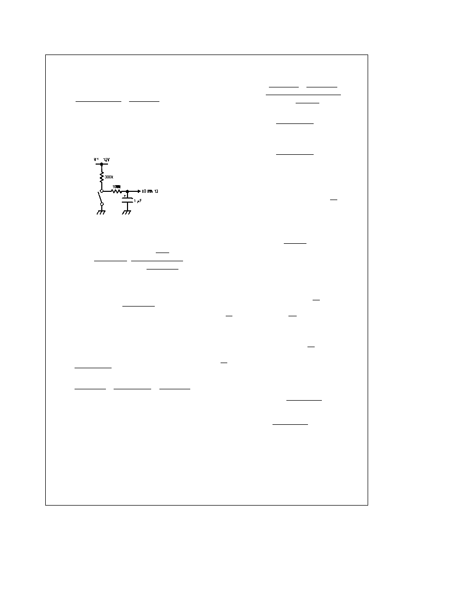
It may be necessary to slow the transition of the logic pin if
the mute circuit is not used The forward and reverse pre-
amplifier output DC voltages can differ by g100 mV This
rapid DC charge is gained up by the output amplifier and
appears as a pop The circuit of
Figure 8 will slow the DC
transition
TLH7902 – 17
FIGURE 8 Circuit to Slow Logic
DESIGN EQUATIONS
The overall gain of the circuit is given by
Av e 25
b
R4R3
R2(R3 a R4)
(
s a
1
R4C1
J
sa 1
(R3 a R4)C1
J
(1)
Standard cassette tapes require equalization of 3180 ms (50
Hz) and 120 ms (13 kHz) These time constants result in an
AC gain at 1 kHz given by
Av (1 kHz) e 25
bR4R3
R2(R3 a R4)
J 1663
(2)
3180 msor50Hz
and
120 ms or 1326 Hz
(
Using the pole and zero locations of the transfer function
the two other equations needed to solve for the component
values are
R4 e
1
2qC1(1326 Hz)
(3)
R3 e
1
2qC1(50 Hz)
b
1
2qC1(1326 Hz)
e
1
2qC1(5196)
(4)
We can now solve for C1 as a function of R2 or
Av (1 kHz) eb25 )
1
2qC1(1326)
(
1
2qC1(5196)
(
R2
1
2qC1(50)
(
*
(1663)
(5)
C1 e
b
480 c 10b3
R2 Av (1 kHz)
(6)
When chromium dioxide is used the defined time constants
are 3180 ms and 70 ms This changes equation (3) to
R4 e
1
2qC1(2274 Hz)
(7)
The value of R3 is normally not changed This results in an
error of less than 02 dB in the low frequency response
The output voltage of the LM1837 is set by the input amplifi-
er DC voltage at pin 5 or 14 and by R3 and R5
Nominal VOUT (pin 2 or 17) e 25
1aR3R5J (8)
Pins 1 and 18 are biased 07V less than VOUT(pin 2 or 17)
When these diodes are used the output (pin 2 or 17) should
be biased at one half the minimum operating supply voltage
Equation (8) can be rewritten to solve for R5
R5 e
25 R3
VO b 25
(9)
The output voltage of the LM1837 will vary from that given
in equation (8) due to variations in the input amplifier DC
voltage as well as the output amplifier input bias current
input offset current and input offset voltage The following
equation gives the worst-case variation in the output voltage
in either forward or reverse state
D
VOUT e g DVPIN3
1aR3R5J a
(10)
R3
R2
DIBIAS(R1bR2)aIOS2(R1aR2)aVOSJ(
Using the worst-case values in the electrical characteristics
reduces this to
D
VOUT e g 04
1aR3R5J a
(11)
R3
R2
200nA(R1bR2)a50nA(R1aR2)a5mVJ(
Equation (10) does not incorporate the effect of mute resis-
tors on the output voltage The presence of mute resistors
causes an additional offset
D
VOUT(mute) e g
D
V(pins 5 – 14)
2(R1 a R7)
c
R1
(12)
For the circuit in
Figure 1 worst-case
D
VOUT(mute) e
400 mV
2(20k a 270k)
c
15M e 1V
This means that the output pins 2 and 17 would differ by 1V
The trade off here is the amount of unmute voltage versus
the DC accuracy of pins 2 and 17
10
Obsolete
相关PDF资料 |
PDF描述 |
|---|---|
| LM1837M | 2 CHANNEL, AUDIO PREAMPLIFIER, PDSO16 |
| LM1851N | POWER SUPPLY SUPPORT CKT, PDIP8 |
| LM1851M | POWER SUPPLY SUPPORT CKT, PDSO8 |
| LM1865MX | FM, AUDIO DEMODULATOR, PDSO20 |
| LM1875DWF | 25 W, 1 CHANNEL, AUDIO AMPLIFIER, UUC |
相关代理商/技术参数 |
参数描述 |
|---|---|
| LM1837N/A+ | 制造商:未知厂家 制造商全称:未知厂家 功能描述:Preamp/Equalizer for Audio Tape Recorder |
| LM1837N/B+ | 制造商:未知厂家 制造商全称:未知厂家 功能描述:Preamp/Equalizer for Audio Tape Recorder |
| LM185 | 制造商:Texas Instruments 功能描述: |
| LM185_08 | 制造商:NSC 制造商全称:National Semiconductor 功能描述:Adjustable Micropower Voltage References |
| LM1851 | 制造商:Rochester Electronics LLC 功能描述: 制造商:Texas Instruments 功能描述: |
发布紧急采购,3分钟左右您将得到回复。