- 您现在的位置:买卖IC网 > PDF目录30743 > LM1881MX-X/NOPB (NATIONAL SEMICONDUCTOR CORP) SYNC SEPARATOR IC, PDSO8 PDF资料下载
参数资料
| 型号: | LM1881MX-X/NOPB |
| 厂商: | NATIONAL SEMICONDUCTOR CORP |
| 元件分类: | 信号分离 |
| 英文描述: | SYNC SEPARATOR IC, PDSO8 |
| 封装: | PLASTIC, SO-8 |
| 文件页数: | 5/11页 |
| 文件大小: | 275K |
| 代理商: | LM1881MX-X/NOPB |
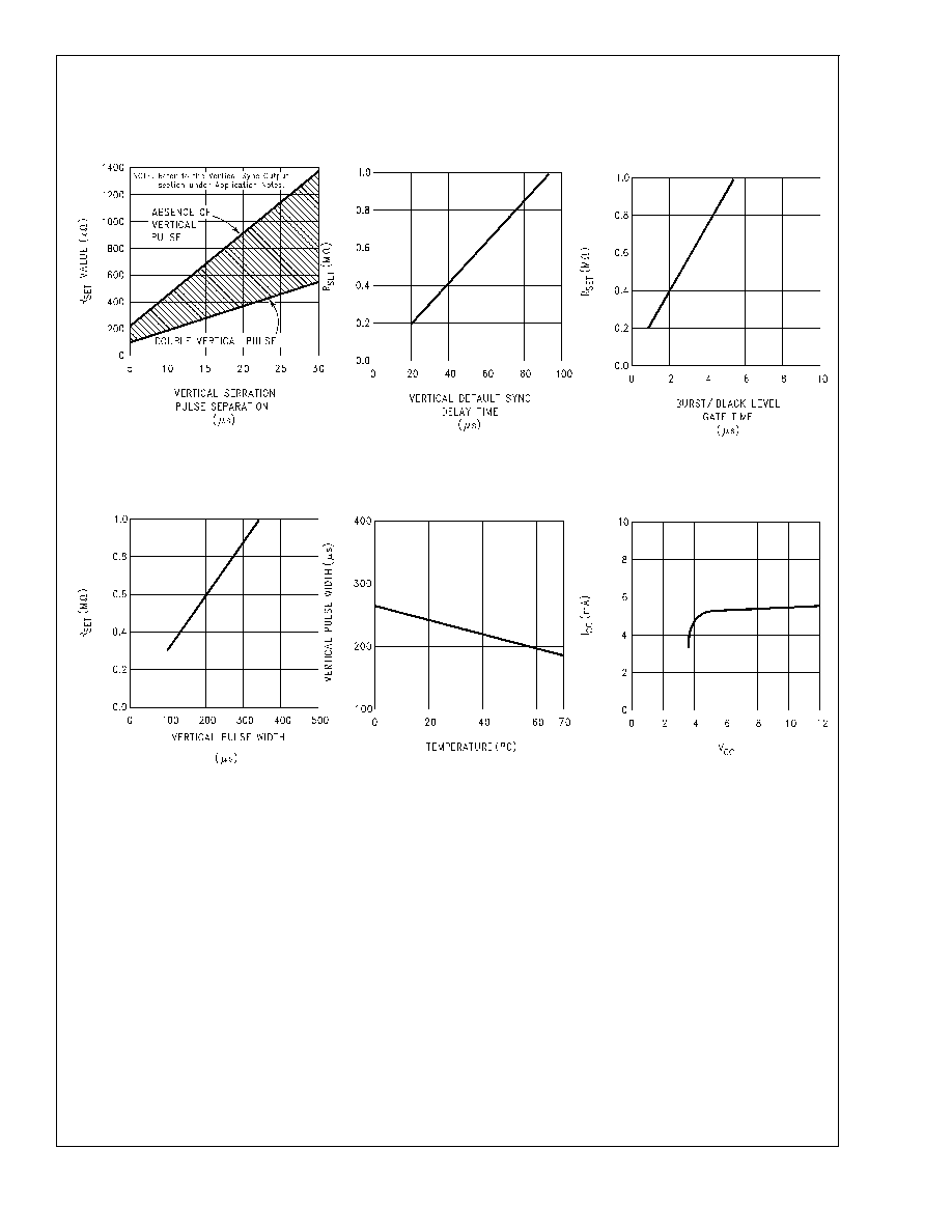
Typical Performance Characteristics
Application Notes
The LM1881 is designed to strip the synchronization signals
from composite video sources that are in, or similar to, the
N.T.S.C. format. Input signals with positive polarity video
(increasing signal voltage signifies increasing scene bright-
ness) from 0.5V (p-p) to 2V (p-p) can be accommodated.
The LM1881 operates from a single supply voltage between
5V DC and 12V DC. The only required external components
besides a power supply decoupling capacitor at pin 8 and a
set current decoupling capacitor at pin 6, are the composite
input coupling capacitor at pin 2 and one resistor at pin 6 that
sets internal current levels. The resistor on pin 6 (i.e. R
set)
allows the LM1881 to be adjusted for source signals with line
scan frequencies differing from 15.734 kHz. Four major sync
signals are available from the I/C; composite sync including
both horizontal and vertical scan timing information; a verti-
cal sync pulse; a burst gate or back porch clamp pulse; and
an odd/even output. The odd/even output level identifies
which video field of an interlaced video source is present at
the input. The outputs from the LM1881 can be used to
gen-lock video camera/VTR signals with graphics sources,
provide identification of video fields for memory storage,
recover suppressed or contaminated sync signals, and pro-
vide timing references for the extraction of coded or uncoded
data on specific video scan lines.
To better understand the LM1881 timing information and the
type of signals that are used, refer to
Figure 1(a-e) which
shows a portion of the composite video signal from the end
of one field through the beginning of the next field.
COMPOSITE SYNC OUTPUT
The composite sync output,
Figure 1(b), is simply a repro-
duction of the signal waveform below the composite video
black level, with the video completely removed. This is ob-
tained by clamping the video signal sync tips to 1.5V DC at
Pin 2 and using a comparator threshold set just above this
voltage to strip the sync signal, which is then buffered out to
Pin 1. The threshold separation from the clamped sync tip is
nominally 70 mV which means that for the minimum input
level of 0.5V (p-p), the clipping level is close to the halfway
point on the sync pulse amplitude (shown by the dashed line
R
SET Value Selection
vs Vertical Serration
Pulse Separation
DS009150-7
Vertical Default
Sync Delay Time
vs R
SET
DS009150-8
Burst/Black Level
Gate Time vs R
SET
DS009150-9
Vertical Pulse
Width vs R
SET
DS009150-10
Vertical Pulse
Width vs Temperature
DS009150-11
Supply Current vs
Supply Voltage
DS009150-2
LM1881
www.national.com
3
相关PDF资料 |
PDF描述 |
|---|---|
| LM1881N-X/NOPB | SYNC SEPARATOR IC, PDIP8 |
| LM1882-RCMX | SPECIALTY CONSUMER CIRCUIT, PDSO20 |
| 54ACT715-RD | SPECIALTY CONSUMER CIRCUIT, CDIP20 |
| 54ACT715D | SPECIALTY CONSUMER CIRCUIT, CDIP20 |
| 54ACT715-RLX | SPECIALTY CONSUMER CIRCUIT, CQCC20 |
相关代理商/技术参数 |
参数描述 |
|---|---|
| LM1881N | 功能描述:视频 IC RoHS:否 制造商:Fairchild Semiconductor 工作电源电压:5 V 电源电流:80 mA 最大工作温度:+ 85 C 封装 / 箱体:TSSOP-28 封装:Reel |
| LM1881N | 制造商:Texas Instruments 功能描述:VIDEO SYNC SEPARATOR 1881 DIP8 |
| LM1881N/NOPB | 功能描述:视频 IC RoHS:否 制造商:Fairchild Semiconductor 工作电源电压:5 V 电源电流:80 mA 最大工作温度:+ 85 C 封装 / 箱体:TSSOP-28 封装:Reel |
| LM1881N/NOPB | 制造商:Texas Instruments 功能描述:Special Function IC |
| LM1881N-8/NOPB | 制造商:Texas Instruments 功能描述: |
发布紧急采购,3分钟左右您将得到回复。