- 您现在的位置:买卖IC网 > PDF目录30744 > LM1882-RL (NATIONAL SEMICONDUCTOR CORP) SPECIALTY CONSUMER CIRCUIT, CQCC20 PDF资料下载
参数资料
| 型号: | LM1882-RL |
| 厂商: | NATIONAL SEMICONDUCTOR CORP |
| 元件分类: | 消费家电 |
| 英文描述: | SPECIALTY CONSUMER CIRCUIT, CQCC20 |
| 封装: | CERAMIC, LCC-20 |
| 文件页数: | 15/19页 |
| 文件大小: | 383K |
| 代理商: | LM1882-RL |
Signal Specification (Continued)
HORIZONTAL AND VERTICAL GATING SIGNALS
Horizontal Drive and Vertical Drive outputs can be utilized as
general purpose Gating Signals. Horizontal and Vertical Gat-
ing Signals are available for use when Composite Sync and
Blank signals are selected and the value of Bit 2 of the Sta-
tus Register is 0. The Vertical Gating signal will change in the
same manner as that specified for the Vertical Blank.
Horizontal Gating Signal Width = [REG(16) REG(15)] x
ckper
Vertical Gating Signal Width:
= [REG(18) REG(17)] x
hper
CURSOR POSITION AND VERTICAL INTERRUPT
The Cursor Position and Vertical Interrupt signal are avail-
able when Composite Sync and Blank signals are selected
and Bit 2 of the Status Register is set to the value of 1. The
Cursor Position generates a single pulse of n clocks wide
during every line that the cursor is specified. The signals are
generated by logically ORing (ANDing) the active LOW
(HIGH) signals specified by the registers used for generating
Horizontal and Vertical Gating signals. The Vertical Interrupt
signal generates a pulse during the vertical interval speci-
fied. The Vertical Interrupt signal will change in the same
manner as that specified for the Vertical Blanking signal.
Horizontal Cursor Width = [REG(16) REG(15)] x ckper
Vertical Cursor Width = [REG(18) REG(17)] x hper
Vertical Interrupt Width = [REG(14) REG(13)] x hper
Addressing Logic
The register addressing logic is composed of two blocks of
logic. The first is the address register and counter (AD-
DRCNTR), and the second is the address decode (AD-
DRDEC).
ADDRCNTR LOGIC
Addresses for the data registers can be generated by one of
two methods. Manual addressing requires that each byte of
each register that needs to be loaded needs to be ad-
dressed. To load both bytes of all 19 registers would require
a total of 57 load cycles (19 address and 38 data cycles).
Auto Addressing requires that only the initial register value
be specified. The Auto Load sequence would require only 39
load cycles to completely program all registers (1 address
and 38 data cycles). In the auto load sequence the low order
byte of the data register will be written first followed by the
high order byte on the next load cycle. At the time the High
Byte is written the address counter is incremented by 1. The
counter has been implemented to loop on the initial value
loaded into the address register. For example: If a value of 0
was written into the address register then the counter would
count from 0 to 18 before resetting back to 0. If a value of 15
was written into the address register then the counter would
count from 15 to 18 before looping back to 15. If a value
greater than or equal to 18 is placed into the address register
the counter will continuously loop on this value. Auto ad-
dressing is initiated on the falling edge of LOAD when AD-
DRDATA is 0 and LHBYTE is 1. Incrementing and loading of
data registers will not commence until the falling edge of
LOAD after ADDRDATA goes to 1. The next rising edge of
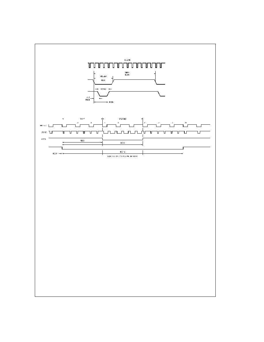
DS100232-5
FIGURE 2. Vertical Waveform Specification
DS100232-12
FIGURE 3. Equalization/Serration Interval Programming
www.national.com
5
相关PDF资料 |
PDF描述 |
|---|---|
| LM1882-RP | SPECIALTY CONSUMER CIRCUIT, PDIP20 |
| LM1882-RS | SPECIALTY CONSUMER CIRCUIT, PDSO20 |
| LM1882D | SPECIALTY CONSUMER CIRCUIT, CDIP20 |
| LM1882L | SPECIALTY CONSUMER CIRCUIT, CQCC20 |
| LM1882P | SPECIALTY CONSUMER CIRCUIT, PDIP20 |
相关代理商/技术参数 |
参数描述 |
|---|---|
| LM1884 | 制造商:NSC 制造商全称:National Semiconductor 功能描述:TV STEREO DECODER |
| LM1884N | 制造商:NSC 制造商全称:National Semiconductor 功能描述:TV STEREO DECODER |
| LM1886 | 制造商:NSC 制造商全称:National Semiconductor 功能描述:TV Video Matrix D to A |
| LM1886N | 制造商:Texas Instruments 功能描述: |
| LM1886N/B+ | 制造商:未知厂家 制造商全称:未知厂家 功能描述:Color Encoder Circuit |
发布紧急采购,3分钟左右您将得到回复。