- 您现在的位置:买卖IC网 > PDF目录44547 > LM2575-12IKTGR (TEXAS INSTRUMENTS INC) 3.2 A SWITCHING REGULATOR, 63 kHz SWITCHING FREQ-MAX, PSSO5 PDF资料下载
参数资料
| 型号: | LM2575-12IKTGR |
| 厂商: | TEXAS INSTRUMENTS INC |
| 元件分类: | 稳压器 |
| 英文描述: | 3.2 A SWITCHING REGULATOR, 63 kHz SWITCHING FREQ-MAX, PSSO5 |
| 封装: | POWER FLEX, PLASTIC, 5 PIN |
| 文件页数: | 9/13页 |
| 文件大小: | 188K |
| 代理商: | LM2575-12IKTGR |
LM2575
1A SIMPLE STEPDOWN SWITCHING VOLTAGE REGULATOR
SLVS569A JANUARY 2005 REVISED FEBRUARY 2005
5
POST OFFICE BOX 655303
DALLAS, TEXAS 75265
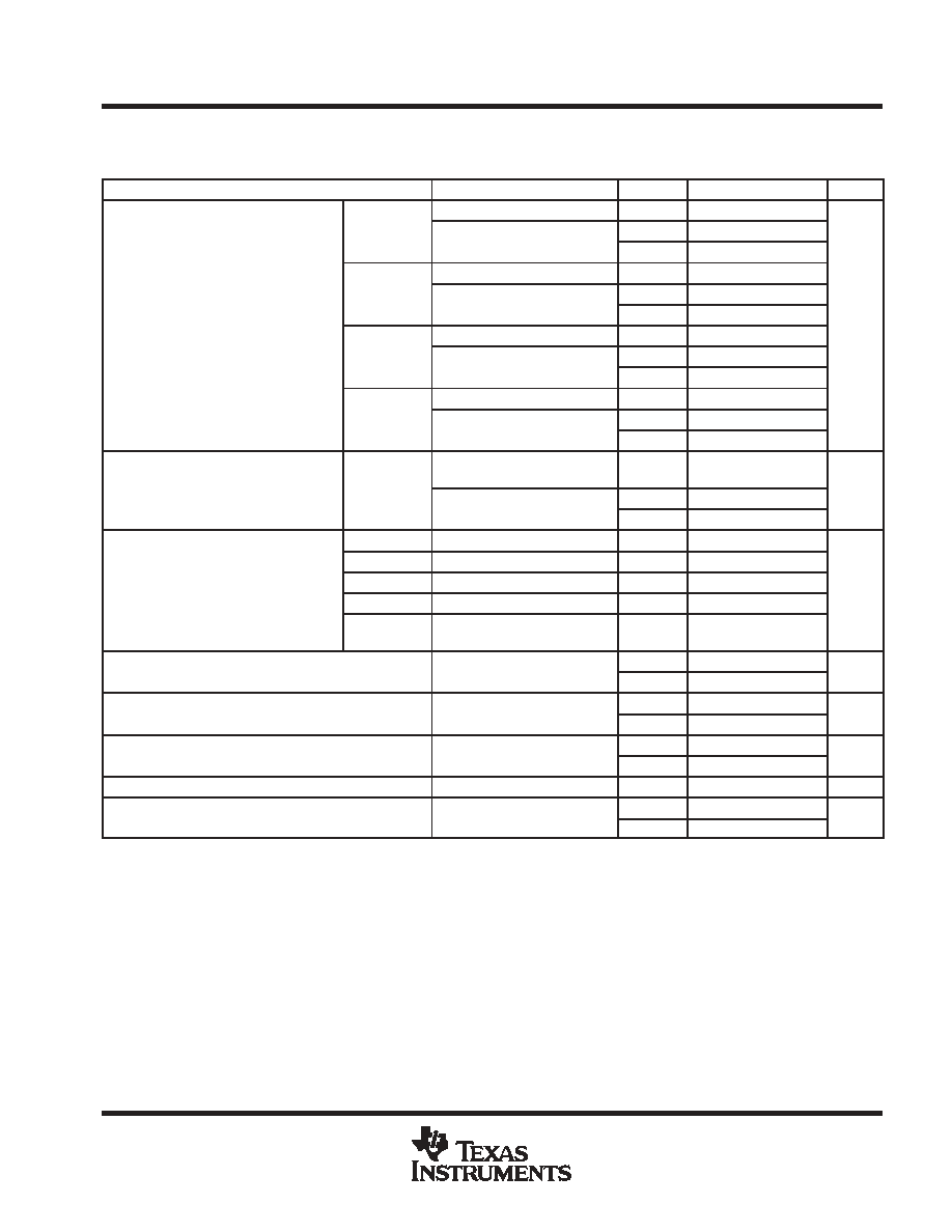
electrical characteristics at ILOAD = 200 mA; VIN = 12 V for the 3.3-V, 5-V, and adjustable versions;
VIN = 25 V for the 12-V version; VIN = 30 V for the 15-V version (unless otherwise noted)
(see Figure 2)
PARAMETER
TEST CONDITIONS
TJ
MIN
TYP
MAX
UNIT
VIN = 12 V, ILOAD = 0.2 A
25
°C
3.234
3.3
3.366
LM2575-33
4.75 V
≤ VIN ≤ 40 V,
25
°C
3.168
3.3
3.432
LM2575-33
4.75 V
≤ VIN ≤ 40 V,
0.2 A
≤ ILOAD ≤ 1 A
Full range
3.135
3.465
VIN = 12 V, ILOAD = 0.2 A
25
°C
4.9
5
5.1
LM2575-05
8 V
≤ VIN ≤ 40 V,
25
°C
4.8
5
5.2
VOUT
Output voltage
LM2575-05
8 V
≤ VIN ≤ 40 V,
0.2 A
≤ ILOAD ≤ 1 A
Full range
4.75
5.25
V
VOUT
Output voltage
VIN = 25 V, ILOAD = 0.2 A
25
°C
11.76
12
12.24
V
LM2575-12
15 V
≤ VIN ≤ 40 V,
25
°C
11.52
12
12.48
LM2575-12
15 V
≤ VIN ≤ 40 V,
0.2 A
≤ ILOAD ≤ 1 A
Full range
11.4
12.6
VIN = 30 V, ILOAD = 0.2 A
25
°C
14.7
15
15.3
LM2575-15
18 V
≤ VIN ≤ 40 V,
25
°C
14.4
15
15.6
LM2575-15
18 V
≤ VIN ≤ 40 V,
0.2 A
≤ ILOAD ≤ 1 A
Full range
14.25
15
15.75
Feedback voltage
LM2575-ADJ
VIN = 12 V, VOUT = 5 V,
ILOAD = 0.2 A
25
°C
1.217
1.23
1.243
V
Feedback voltage
LM2575-ADJ
8 V
≤ VIN ≤ 40 V, VOUT = 5 V,
25
°C
1.193
1.23
1.267
V
8 V
≤ VIN ≤ 40 V, VOUT = 5 V,
0.2 A
≤ ILOAD ≤ 1 A
Full range
1.18
1.28
LM2575-33
VIN = 12 V, ILOAD = 1 A
25
°C
75
LM2575-05
VIN = 12 V, ILOAD = 1 A
25
°C
77
η
Efficiency
LM2575-12
VIN = 15 V, ILOAD = 1 A
25
°C
88
%
η
Efficiency
LM2575-15
VIN = 18 V, ILOAD = 1 A
25
°C
88
%
LM2575-ADJ
VIN = 12 V, VOUT = 5 V,
ILOAD = 1 A
25
°C
77
IIB
Feedback bias current
VOUT = 5 V
25
°C
50
100
nA
IIB
Feedback bias current
VOUT = 5 V
(ADJ version only)
Full range
500
nA
fo
Oscillator frequency
See Note 2
25
°C
47
52
58
kHz
fo
Oscillator frequency
See Note 2
Full range
42
63
kHz
VSAT
Saturation voltage
IOUT = 1 A (see Note 3)
25
°C
0.9
1.2
V
VSAT
Saturation voltage
IOUT = 1 A (see Note 3)
Full range
1.4
V
Max duty cycle
See Note 4
25
°C
93
98
%
ICL
Peak current
See Notes 2 and 3
25
°C
1.7
2.2
3
A
ICL
Peak current
See Notes 2 and 3
Full range
1.3
3.2
A
NOTES:
2. In the event of an output short or an overload condition, self-protection features lower the oscillator frequency to
18 kHz and the
minimum duty cycle from 5% to
2%. The resulting output voltage drops to 40% of its nominal value, causing the average power
dissipated by the IC to lower.
3. Output is not connected to diode, inductor, or capacitor. Output is sourcing current.
4. Feedback is disconnected from output and connected to 0 V.
PRODUCT
PREVIEW
相关PDF资料 |
PDF描述 |
|---|---|
| LM2575-15IKC | 3.2 A SWITCHING REGULATOR, 63 kHz SWITCHING FREQ-MAX, PSFM5 |
| LM2575T-5.0-VT | 3.2 A SWITCHING REGULATOR, 62 kHz SWITCHING FREQ-MAX, PSFM5 |
| LM2575S-12TRT | 3.2 A SWITCHING REGULATOR, 62 kHz SWITCHING FREQ-MAX, PSSO5 |
| LM2576T-ADJ-H | 7.5 A SWITCHING REGULATOR, 62 kHz SWITCHING FREQ-MAX, PSFM5 |
| LM2576S-ADJTR | 7.5 A SWITCHING REGULATOR, 62 kHz SWITCHING FREQ-MAX, PSSO5 |
相关代理商/技术参数 |
参数描述 |
|---|---|
| LM2575-12IKTT | 制造商:TI 制造商全称:Texas Instruments 功能描述:1-A SIMPLE STEP DOWN SWITCHING VOLTAGE REGULATOR |
| LM2575-12IKTTR | 制造商:TI 制造商全称:Texas Instruments 功能描述:1-A SIMPLE STEP DOWN SWITCHING VOLTAGE REGULATOR |
| LM2575-12IN | 制造商:TI 制造商全称:Texas Instruments 功能描述:1-A SIMPLE STEP DOWN SWITCHING VOLTAGE REGULATOR |
| LM2575-12T | 制造商:未知厂家 制造商全称:未知厂家 功能描述:Easy Switcher 1.0 A Step-Down Voltage Regulator(389.50 k) |
| LM2575-12TA5R | 制造商:FCI 制造商全称:First Components International 功能描述:1.0A Step - Down Voltage Switching Regulators 1A output current |
发布紧急采购,3分钟左右您将得到回复。