- 您现在的位置:买卖IC网 > PDF目录30746 > LM2575N-5.0EP (NATIONAL SEMICONDUCTOR CORP) 3.2 A SWITCHING REGULATOR, 63 kHz SWITCHING FREQ-MAX, PDIP16 PDF资料下载
参数资料
| 型号: | LM2575N-5.0EP |
| 厂商: | NATIONAL SEMICONDUCTOR CORP |
| 元件分类: | 稳压器 |
| 英文描述: | 3.2 A SWITCHING REGULATOR, 63 kHz SWITCHING FREQ-MAX, PDIP16 |
| 封装: | DIP-16 |
| 文件页数: | 6/26页 |
| 文件大小: | 1069K |
| 代理商: | LM2575N-5.0EP |
Inductor Value Selection Guides (For Continuous Mode Operation) (Continued)
PROCEDURE (Adjustable Output Voltage Versions)
EXAMPLE (Adjustable Output Voltage Versions)
Given: V
OUT = Regulated Output Voltage VIN(Max) =
Maximum Input Voltage I
LOAD(Max) = Maximum Load
Current F = Switching Frequency (Fixed at 52 kHz)
Given: V
OUT = 10V VIN(Max) = 25V ILOAD(Max) = 1A F =
52 kHz
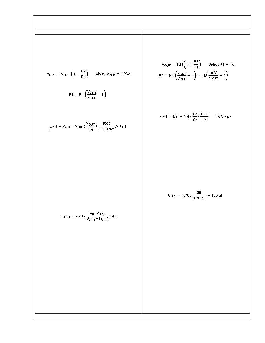
1. Programming Output Voltage (Selecting R1 and R2, as
shown in Figure 2 ) Use the following formula to select the
appropriate resistor values.
R
1 can be between 1k and 5k. (For best temperature coef-
ficient and stability with time, use 1% metal film resistors)
1.Programming Output Voltage (Selecting R1 and R2)
R2 = 1k (8.13 1) = 7.13k, closest 1% value is 7.15k
2. Inductor Selection (L1) A. Calculate the inductor Volt
microsecond constant, E
T(V s), from the following
formula:
B. Use the E
T value from the previous formula and match
it with the E
T number on the vertical axis of the Inductor
Value Selection Guide shown in Figure 7. C. On the hori-
zontal axis, select the maximum load current. D. Identify the
inductance region intersected by the E
T value and the
maximum load current value, and note the inductor code for
that region. E. Identify the inductor value from the inductor
code, and select an appropriate inductor from the table shown
in Figure 9. Part numbers are listed for three inductor manu-
facturers. The inductor chosen must be rated for operation at
the LM2575EP switching frequency (52 kHz) and for a current
rating of 1.15 x I
LOAD. For additional inductor information, see
the inductor section in the application hints section of this data
sheet.
2. Inductor Selection (L1) A. Calculate E
T(V s)
B. E
T = 115 V s C. I
LOAD(Max) = 1A D. Inductance
Region = H470 E. Inductor Value = 470 H Choose from AIE
part #430-0634, Pulse Engineering part #PE-53118, or
Renco part #RL-1961.
3. Output Capacitor Selection (C
OUT)A. The value of the
output capacitor together with the inductor defines the
dominate pole-pair of the switching regulator loop. For
stable operation, the capacitor must satisfy the following
requirement:
The above formula yields capacitor values between 10 F
and 2000 F that will satisfy the loop requirements for stable
operation. But to achieve an acceptable output ripple voltage,
(approximately 1% of the output voltage) and transient re-
sponse, the output capacitor may need to be several times
larger than the above formula yields. B. The capacitor’s volt-
age rating should be at last 1.5 times greater than the output
voltage. For a 10V regulator, a rating of at least 15V or more
is recommended. Higher voltage electrolytic capacitors gen-
erally have lower ESR numbers, and for this reason it may be
necessary to select a capacitor rate for a higher voltage than
would normally be needed.
3. Output Capacitor Selection (C
OUT)A.
However, for acceptable output ripple voltage select C
OUT
≥
220 F C
OUT = 220 F electrolytic capacitor
4. Catch Diode Selection (D1) A. The catch-diode current
rating must be at least 1.2 times greater than the maximum
load current. Also, if the power supply design must
withstand a continuous output short, the diode should have
a current rating equal to the maximum current limit of the
LM2575EP. The most stressful condition for this diode is an
overload or shorted output. See diode selection guide in
Figure 8. B. The reverse voltage rating of the diode should
be at least 1.25 times the maximum input voltage.
4. Catch Diode Selection (D1) A. For this example, a 3A
current rating is adequate. B. Use a 40V MBR340 or
31DQ04 Schottky diode, or any of the suggested
fast-recovery diodes in Figure 8.
LM2575EP/LM2575HVEP
www.national.com
14
相关PDF资料 |
PDF描述 |
|---|---|
| LM2575HVMX-12EP | 3.2 A SWITCHING REGULATOR, 63 kHz SWITCHING FREQ-MAX, PSSO5 |
| LM2575HVM-5.0EP | 3.2 A SWITCHING REGULATOR, 63 kHz SWITCHING FREQ-MAX, PSSO5 |
| LM2575SX-15EP | 3.2 A SWITCHING REGULATOR, 63 kHz SWITCHING FREQ-MAX, PSSO5 |
| LM2575MX-5.0EP | 3.2 A SWITCHING REGULATOR, 63 kHz SWITCHING FREQ-MAX, PDSO24 |
| LM2575S-12EP | 3.2 A SWITCHING REGULATOR, 63 kHz SWITCHING FREQ-MAX, PSSO5 |
相关代理商/技术参数 |
参数描述 |
|---|---|
| LM2575NADJ | 制造商:NATIONAL 功能描述:* |
| LM2575N-ADJ | 功能描述:直流/直流开关转换器 RoHS:否 制造商:STMicroelectronics 最大输入电压:4.5 V 开关频率:1.5 MHz 输出电压:4.6 V 输出电流:250 mA 输出端数量:2 最大工作温度:+ 85 C 安装风格:SMD/SMT |
| LM2575N-ADJ/NOPB | 功能描述:直流/直流开关转换器 RoHS:否 制造商:STMicroelectronics 最大输入电压:4.5 V 开关频率:1.5 MHz 输出电压:4.6 V 输出电流:250 mA 输出端数量:2 最大工作温度:+ 85 C 安装风格:SMD/SMT |
| LM2575R | 制造商:HTC 制造商全称:HTC Korea TAEJIN Technology Co. 功能描述:1A, 52kHz, Step-Down Switching Regulator |
| LM2575S | 制造商:SEMTECH 制造商全称:Semtech Corporation 功能描述:1A & 3A Miniconverter Switching Regulators |
发布紧急采购,3分钟左右您将得到回复。