- 您现在的位置:买卖IC网 > PDF目录80330 > LM2575TV-15 (MOTOROLA INC) 3.2 A SWITCHING REGULATOR, 52 kHz SWITCHING FREQ-MAX, PZFM5 PDF资料下载
参数资料
| 型号: | LM2575TV-15 |
| 厂商: | MOTOROLA INC |
| 元件分类: | 稳压器 |
| 英文描述: | 3.2 A SWITCHING REGULATOR, 52 kHz SWITCHING FREQ-MAX, PZFM5 |
| 封装: | 314B-05 |
| 文件页数: | 8/28页 |
| 文件大小: | 380K |
| 代理商: | LM2575TV-15 |
第1页第2页第3页第4页第5页第6页第7页当前第8页第9页第10页第11页第12页第13页第14页第15页第16页第17页第18页第19页第20页第21页第22页第23页第24页第25页第26页第27页第28页
LM2575
16
MOTOROLA ANALOG IC DEVICE DATA
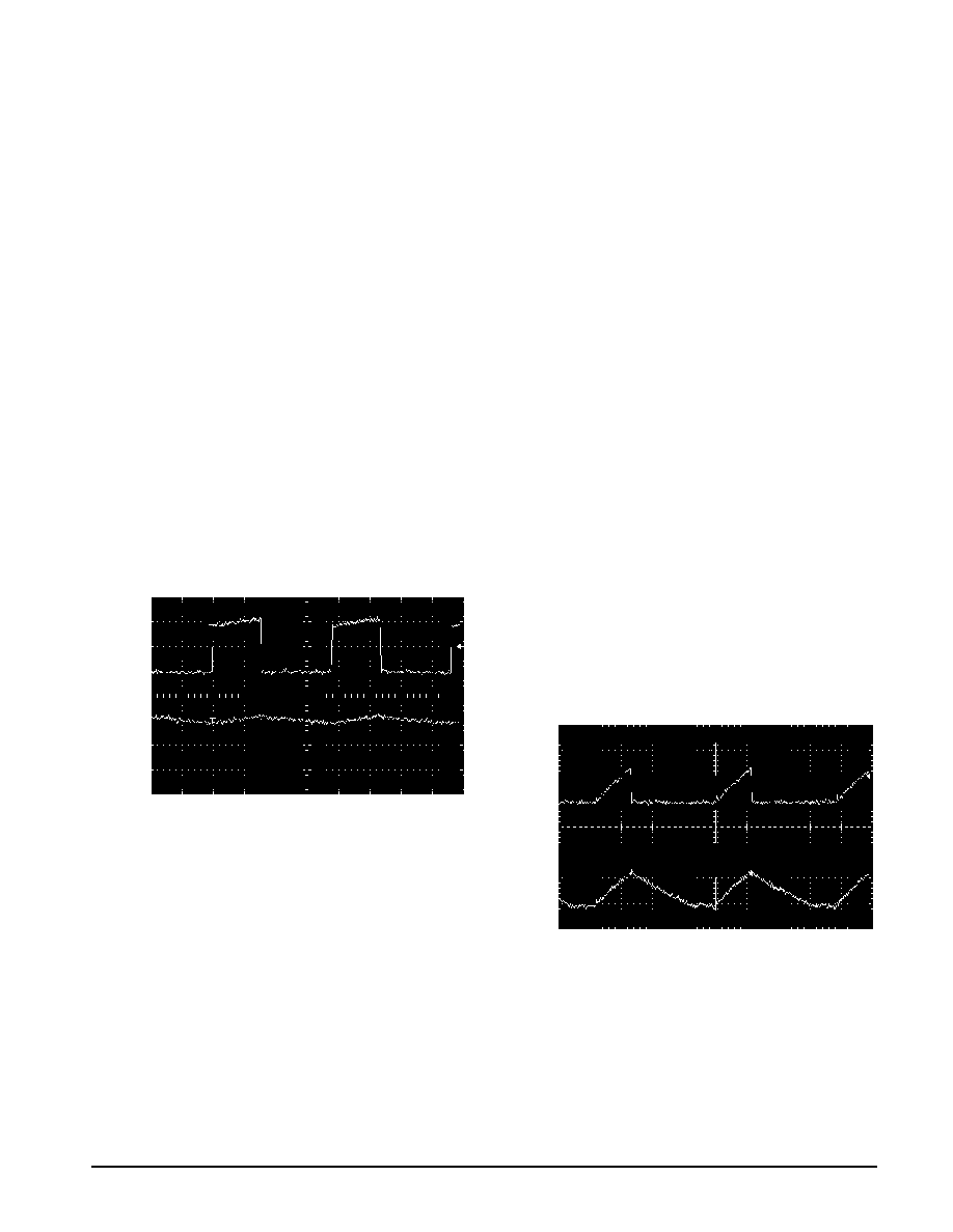
conditions, the circuit will be forced to the discontinuous
mode when inductor current falls to zero for certain period of
time (see Figure 22 and Figure 23). Each mode has
distinctively different operating characteristics, which can
affect the regulator performance and requirements. In many
cases the preferred mode of operation is the continuous
mode. It offers greater output power, lower peak currents in
the switch, inductor and diode, and can have a lower output
ripple voltage. On the other hand it does require larger
inductor values to keep the inductor current flowing
continuously, especially at low output load currents and/or
high input voltages.
To simplify the inductor selection process, an inductor
selection guide for the LM2575 regulator was added to this
data sheet (Figures 17 through 21). This guide assumes that
the regulator is operating in the continuous mode, and
selects an inductor that will allow a peak–to–peak inductor
ripple current to be a certain percentage of the maximum
design load current. This percentage is allowed to change as
different design load currents are selected. For light loads
(less than approximately 200 mA) it may be desirable to
operate the regulator in the discontinuous mode, because
the inductor value and size can be kept relatively low.
Consequently, the percentage of inductor peak–to–peak
current increases. This discontinuous mode of operation is
perfectly acceptable for this type of switching converter. Any
buck regulator will be forced to enter discontinuous mode if
the load current is light enough.
Figure 22. Continuous Mode Switching
Current Waveforms
POWER
SWITCH
1.0
0
CURRENT
(A)
HORTIZONTAL TIME BASE: 5.0
s/DIV
1.0
INDUCT
OR
CURRENT
(A)
Selecting the Right Inductor Style
Some important considerations when selecting a core
type are core material, cost, the output power of the power
supply, the physical volume the inductor must fit within, and
the amount of EMI (Electro–Magnetic Interference) shielding
that the core must provide. The inductor selection guide
covers different styles of inductors, such as pot core, E–core,
toroid and bobbin core, as well as different core materials
such as ferrites and powdered iron from different
manufacturers.
For high quality design regulators the toroid core seems to
be the best choice. Since the magnetic flux is completely
contained within the core, it generates less EMI, reducing
noise problems in sensitive circuits. The least expensive is
the bobbin core type, which consists of wire wound on a
ferrite rod core. This type of inductor generates more EMI
due to the fact that its core is open, and the magnetic flux is
not completely contained within the core.
When multiple switching regulators are located on the
same printed circuit board, open core magnetics can cause
interference between two or more of the regulator circuits,
especially at high currents due to mutual coupling. A toroid,
pot core or E–core (closed magnetic structure) should be
used in such applications.
Do Not Operate an Inductor Beyond its
Maximum Rated Current
Exceeding an inductor’s maximum current rating may
cause the inductor to overheat because of the copper wire
losses, or the core may saturate. Core saturation occurs
when the flux density is too high and consequently the cross
sectional area of the core can no longer support additional
lines of magnetic flux.
This causes the permeability of the core to drop, the
inductance value decreases rapidly and the inductor begins
to look mainly resistive. It has only the dc resistance of the
winding. This can cause the switch current to rise very rapidly
and force the LM2575 internal switch into cycle–by–cycle
current limit, thus reducing the dc output load current. This
can also result in overheating of the inductor and/or the
LM2575. Different inductor types have different saturation
characteristics, and this should be kept in mind when
selecting an inductor.
Figure 23. Discontinuous Mode Switching
Current Waveforms
0.1
0
HORTIZONTAL TIME BASE: 5.0
s/DIV
POWER
SWITCH
CURRENT
(A)
INDUCT
OR
CURRENT
(A)
相关PDF资料 |
PDF描述 |
|---|---|
| LM4040D-5MWC | 1-OUTPUT TWO TERM VOLTAGE REFERENCE, 5 V, UUC |
| LM1501-7RV3HF | 1-OUTPUT 50 W AC-DC REG PWR SUPPLY MODULE |
| LM1601-7RV0A | 1-OUTPUT 50 W AC-DC REG PWR SUPPLY MODULE |
| LM1601-7RV3A | 1-OUTPUT 50 W AC-DC REG PWR SUPPLY MODULE |
| LM1601-9RV3F | 1-OUTPUT 50 W AC-DC REG PWR SUPPLY MODULE |
相关代理商/技术参数 |
参数描述 |
|---|---|
| LM2575TV-15G | 功能描述:直流/直流开关调节器 15V 1A Buck PWM RoHS:否 制造商:International Rectifier 最大输入电压:21 V 开关频率:1.5 MHz 输出电压:0.5 V to 0.86 V 输出电流:4 A 输出端数量: 最大工作温度: 安装风格:SMD/SMT 封装 / 箱体:PQFN 4 x 5 |
| LM2575TV-3.3 | 功能描述:直流/直流开关调节器 3.3V 1A Buck PWM RoHS:否 制造商:International Rectifier 最大输入电压:21 V 开关频率:1.5 MHz 输出电压:0.5 V to 0.86 V 输出电流:4 A 输出端数量: 最大工作温度: 安装风格:SMD/SMT 封装 / 箱体:PQFN 4 x 5 |
| LM2575TV-3.3G | 功能描述:直流/直流开关调节器 3.3V 1A Buck PWM RoHS:否 制造商:International Rectifier 最大输入电压:21 V 开关频率:1.5 MHz 输出电压:0.5 V to 0.86 V 输出电流:4 A 输出端数量: 最大工作温度: 安装风格:SMD/SMT 封装 / 箱体:PQFN 4 x 5 |
| LM2575TV-5 | 制造商:ONSEMI 制造商全称:ON Semiconductor 功能描述:1.0 A, Adjustable Output Voltage, Step-Down Switching Regulator |
| LM2575TV-5G | 功能描述:直流/直流开关调节器 5V 1A PWR SW REG RoHS:否 制造商:International Rectifier 最大输入电压:21 V 开关频率:1.5 MHz 输出电压:0.5 V to 0.86 V 输出电流:4 A 输出端数量: 最大工作温度: 安装风格:SMD/SMT 封装 / 箱体:PQFN 4 x 5 |
发布紧急采购,3分钟左右您将得到回复。