- 您现在的位置:买卖IC网 > PDF目录44548 > LM2576T-ADJLB03/NOPB (NATIONAL SEMICONDUCTOR CORP) 3 A SWITCHING REGULATOR, 52 kHz SWITCHING FREQ-MAX, SFM5 PDF资料下载
参数资料
| 型号: | LM2576T-ADJLB03/NOPB |
| 厂商: | NATIONAL SEMICONDUCTOR CORP |
| 元件分类: | 稳压器 |
| 英文描述: | 3 A SWITCHING REGULATOR, 52 kHz SWITCHING FREQ-MAX, SFM5 |
| 封装: | ROHS COMPLIANT, TO-220, 5 PIN |
| 文件页数: | 6/24页 |
| 文件大小: | 750K |
| 代理商: | LM2576T-ADJLB03/NOPB |
LM2576 Series Buck Regulator Design Procedure (Continued)
PROCEDURE (Adjustable Output Voltage Versions)
EXAMPLE (Adjustable Output Voltage Versions)
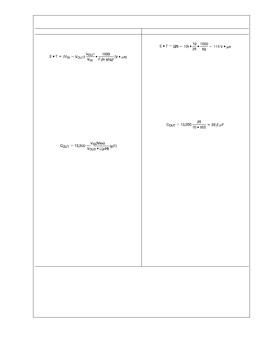
2. Inductor Selection (L1) A. Calculate the inductor Volt
microsecond constant, E T(V s), from the
following formula:
B. Use the E
T value from the previous formula and
match it with the E
T number on the vertical axis of the
Inductor Value Selection Guide shown in Figure 7. C. On
the horizontal axis, select the maximum load current. D.
Identify the inductance region intersected by the E
T
value and the maximum load current value, and note the
inductor code for that region. E. Identify the inductor value
from the inductor code, and select an appropriate inductor
from the table shown in Figure 9. Part numbers are listed
for three inductor manufacturers. The inductor chosen
must be rated for operation at the LM2576 switching fre-
quency (52 kHz) and for a current rating of 1.15 x I
LOAD.
For additional inductor information, see the inductor sec-
tion in the application hints section of this data sheet.
2. Inductor Selection (L1) A. Calculate E
T(V s)
B. E
T = 115 V s C. I
LOAD(Max) = 3A D. Inductance
Region = H150 E. Inductor Value = 150 H Choose from
AIE part #415-0936 Pulse Engineering part #PE-531115,
or Renco part #RL2445.
3. Output Capacitor Selection (C
OUT)A. The value of
the output capacitor together with the inductor defines
the dominate pole-pair of the switching regulator loop.
For stable operation, the capacitor must satisfy the
following requirement:
The above formula yields capacitor values between 10 F
and 2200 F that will satisfy the loop requirements for
stable operation. But to achieve an acceptable output
ripple voltage, (approximately 1% of the output voltage)
and transient response, the output capacitor may need to
be several times larger than the above formula yields. B.
The capacitor’s voltage rating should be at last 1.5 times
greater than the output voltage. For a 10V regulator, a
rating of at least 15V or more is recommended. Higher
voltage electrolytic capacitors generally have lower ESR
numbers, and for this reason it may be necessary to select
a capacitor rate for a higher voltage than would normally be
needed.
3. Output Capacitor Selection (C
OUT)
However, for acceptable output ripple voltage select C
OUT
≥ 680 F C
OUT = 680 F electrolytic capacitor
4. Catch Diode Selection (D1) A. The catch-diode
current rating must be at least 1.2 times greater than the
maximum load current. Also, if the power supply design
must withstand a continuous output short, the diode
should have a current rating equal to the maximum
current limit of the LM2576. The most stressful condition
for this diode is an overload or shorted output. See diode
selection guide in Figure 8. B. The reverse voltage rating
of the diode should be at least 1.25 times the maximum
input voltage.
4. Catch Diode Selection (D1) A. For this example, a
3.3A current rating is adequate. B. Use a 30V 31DQ03
Schottky diode, or any of the suggested fast-recovery
diodes in Figure 8.
5. Input Capacitor (C
IN) An aluminum or tantalum
electrolytic bypass capacitor located close to the
regulator is needed for stable operation.
5. Input Capacitor (C
IN) A 100 F aluminum electrolytic
capacitor located near the input and ground pins
provides sufficient bypassing.
To further simplify the buck regulator design procedure, Na-
tional Semiconductor is making available computer design
software to be used with the SIMPLE SWITCHER line of
switching regulators. Switchers Made Simple (Version 3.3)
is available on a (312") diskette for IBM compatible comput-
ers from a National Semiconductor sales office in your area.
LM2576/LM2576HV
www.national.com
14
相关PDF资料 |
PDF描述 |
|---|---|
| LM2576T-12FLOWLB03 | 3.5 A SWITCHING REGULATOR, 52 kHz SWITCHING FREQ-MAX, PSFM5 |
| LM2576T-12/LB03 | 7.5 A SWITCHING REGULATOR, 63 kHz SWITCHING FREQ-MAX, PSFM5 |
| LM2576HVT-ADJFLOWLB03/NOPB | 7.5 A SWITCHING REGULATOR, 63 kHz SWITCHING FREQ-MAX, ZFM5 |
| LM2576SX-12/NOPB | 7.5 A SWITCHING REGULATOR, 63 kHz SWITCHING FREQ-MAX, PSSO5 |
| LM2576SX-15/NOPB | 7.5 A SWITCHING REGULATOR, 63 kHz SWITCHING FREQ-MAX, PSSO5 |
相关代理商/技术参数 |
参数描述 |
|---|---|
| LM2576T-ADJ-V | 制造商:SEMTECH 制造商全称:Semtech Corporation 功能描述:Voltage-Mode SMPS Controller |
| LM2576TV | 制造商:未知厂家 制造商全称:未知厂家 功能描述:3.0A, 15V, Step-Down Switching Regulator |
| LM2576TV-005 | 功能描述:直流/直流开关调节器 5V 3A Buck PWM RoHS:否 制造商:International Rectifier 最大输入电压:21 V 开关频率:1.5 MHz 输出电压:0.5 V to 0.86 V 输出电流:4 A 输出端数量: 最大工作温度: 安装风格:SMD/SMT 封装 / 箱体:PQFN 4 x 5 |
| LM2576TV-005G | 制造商:ON Semiconductor 功能描述: |
| LM2576TV-012 | 功能描述:直流/直流开关调节器 12V 3A Buck PWM RoHS:否 制造商:International Rectifier 最大输入电压:21 V 开关频率:1.5 MHz 输出电压:0.5 V to 0.86 V 输出电流:4 A 输出端数量: 最大工作温度: 安装风格:SMD/SMT 封装 / 箱体:PQFN 4 x 5 |
发布紧急采购,3分钟左右您将得到回复。