- 您现在的位置:买卖IC网 > PDF目录69004 > LM2576TV-ADJ (MOTOROLA INC) 3 A SWITCHING REGULATOR, 63 kHz SWITCHING FREQ-MAX, PSFM5 PDF资料下载
参数资料
| 型号: | LM2576TV-ADJ |
| 厂商: | MOTOROLA INC |
| 元件分类: | 稳压器 |
| 英文描述: | 3 A SWITCHING REGULATOR, 63 kHz SWITCHING FREQ-MAX, PSFM5 |
| 封装: | TO-220, 5 PIN |
| 文件页数: | 1/28页 |
| 文件大小: | 415K |
| 代理商: | LM2576TV-ADJ |
当前第1页第2页第3页第4页第5页第6页第7页第8页第9页第10页第11页第12页第13页第14页第15页第16页第17页第18页第19页第20页第21页第22页第23页第24页第25页第26页第27页第28页
Device
Operating
Temperature Range
Package
LM2576
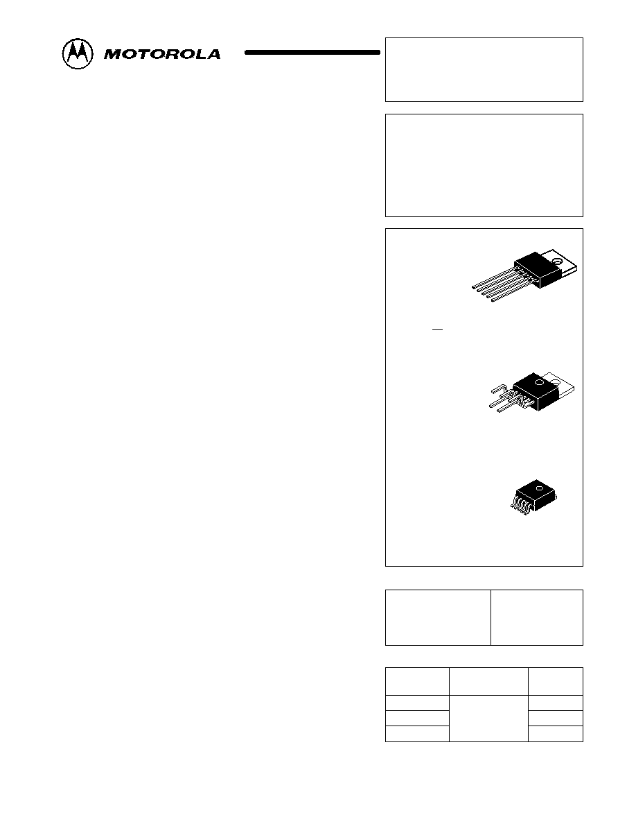
EASY SWITCHER
3.0 A STEP–DOWN
VOLTAGE REGULATOR
ORDERING INFORMATION
LM2576T–XX
LM2576TV–XX
TJ = –40° to +125°C
Straight Lead
Vertical Mount
D2T SUFFIX
PLASTIC PACKAGE
CASE 936A
(D2PAK)
Order this document by LM2576/D
T SUFFIX
PLASTIC PACKAGE
CASE 314D
TV SUFFIX
PLASTIC PACKAGE
CASE 314B
LM2576D2T–XX
Surface Mount
XX = Voltage Option, i.e. 3.3, 5, 12, 15 V; and ADJ for
Adjustable Output.
SEMICONDUCTOR
TECHNICAL DATA
1
5
1
5
1
5
DEVICE TYPE/NOMINAL OUTPUT VOLTAGE
LM2576–3.3
LM2576–5
LM2576–12
LM2576–15
LM2576–ADJ
3.3 V
5.0 V
12 V
15 V
1.23 V to 37 V
Pin 1. Vin
2. Output
3. Ground
4. Feedback
5. ON/OFF
Heatsink surface
connected to Pin 3.
Heatsink surface (shown as terminal 6 in case outline
drawing) is connected to Pin 3.
1
MOTOROLA ANALOG IC DEVICE DATA
Easy Switcher 3.0 A
Step-Down Voltage Regulator
The LM2576 series of regulators are monolithic integrated circuits ideally
suited for easy and convenient design of a step–down switching regulator
(buck converter). All circuits of this series are capable of driving a 3.0 A load
with excellent line and load regulation. These devices are available in fixed
output voltages of 3.3 V, 5.0 V, 12 V, 15 V, and an adjustable output version.
These regulators were designed to minimize the number of external
components to simplify the power supply design. Standard series of
inductors optimized for use with the LM2576 are offered by several different
inductor manufacturers.
Since the LM2576 converter is a switch–mode power supply, its efficiency
is significantly higher in comparison with popular three–terminal linear
regulators, especially with higher input voltages. In many cases, the power
dissipated is so low that no heatsink is required or its size could be reduced
dramatically.
A standard series of inductors optimized for use with the LM2576 are
available from several different manufacturers. This feature greatly simplifies
the design of switch–mode power supplies.
The LM2576 features include a guaranteed
±4% tolerance on output
voltage within specified input voltages and output load conditions, and
±10%
on the oscillator frequency (
±2% over 0°C to 125°C). External shutdown is
included, featuring 80
A (typical) standby current. The output switch
includes cycle–by–cycle current limiting, as well as thermal shutdown for full
protection under fault conditions.
Features
3.3 V, 5.0 V, 12 V, 15 V, and Adjustable Output Versions
Adjustable Version Output Voltage Range, 1.23 to 37 V ±4% Maximum
Over Line and Load Conditions
Guaranteed 3.0 A Output Current
Wide Input Voltage Range
Requires Only 4 External Components
52 kHz Fixed Frequency Internal Oscillator
TTL Shutdown Capability, Low Power Standby Mode
High Efficiency
Uses Readily Available Standard Inductors
Thermal Shutdown and Current Limit Protection
Applications
Simple High–Efficiency Step–Down (Buck) Regulator
Efficient Pre–Regulator for Linear Regulators
On–Card Switching Regulators
Positive to Negative Converter (Buck–Boost)
Negative Step–Up Converters
Power Supply for Battery Chargers
Motorola, Inc. 1999
Rev 1, 07/1999
相关PDF资料 |
PDF描述 |
|---|---|
| LM2623ALDX/NOPB | 2.2 A SWITCHING REGULATOR, 2000 kHz SWITCHING FREQ-MAX, DSO14 |
| LM2651-1.8MWC | 2.6 A SWITCHING REGULATOR, 345 kHz SWITCHING FREQ-MAX, UUC |
| LM2651-3.3MWC | 2.6 A SWITCHING REGULATOR, 345 kHz SWITCHING FREQ-MAX, UUC |
| LM2651-ADJMWC | 2.6 A SWITCHING REGULATOR, 345 kHz SWITCHING FREQ-MAX, UUC |
| LM2651-3.3MDC | 2.6 A SWITCHING REGULATOR, 345 kHz SWITCHING FREQ-MAX, UUC |
相关代理商/技术参数 |
参数描述 |
|---|---|
| LM2576TV-ADJG | 功能描述:直流/直流开关调节器 3A 1.23-37V ADJ Buck PWM RoHS:否 制造商:International Rectifier 最大输入电压:21 V 开关频率:1.5 MHz 输出电压:0.5 V to 0.86 V 输出电流:4 A 输出端数量: 最大工作温度: 安装风格:SMD/SMT 封装 / 箱体:PQFN 4 x 5 |
| LM2576TV-AJD | 制造商:MOTOROLA 制造商全称:Motorola, Inc 功能描述:EASY SWITCHERE⑩ 3.0 A STEP-DOWN VOLTAGE REGULATOR |
| LM2576WT | 功能描述:直流/直流开关调节器 3A Step-Down SMPS Regulator (ROHS Compliant) RoHS:否 制造商:International Rectifier 最大输入电压:21 V 开关频率:1.5 MHz 输出电压:0.5 V to 0.86 V 输出电流:4 A 输出端数量: 最大工作温度: 安装风格:SMD/SMT 封装 / 箱体:PQFN 4 x 5 |
| LM2576WT L3 | 制造商:Micrel Inc 功能描述:Micrel LM2576WT L3 DC to DC Conversion |
| LM2576WU | 功能描述:直流/直流开关调节器 3A Step-Down SMPS Regulator (ROHS Compliant) RoHS:否 制造商:International Rectifier 最大输入电压:21 V 开关频率:1.5 MHz 输出电压:0.5 V to 0.86 V 输出电流:4 A 输出端数量: 最大工作温度: 安装风格:SMD/SMT 封装 / 箱体:PQFN 4 x 5 |
发布紧急采购,3分钟左右您将得到回复。