- 您现在的位置:买卖IC网 > PDF目录44548 > LM2578MWC (NATIONAL SEMICONDUCTOR CORP) 0.75 A SWITCHING REGULATOR, 100 kHz SWITCHING FREQ-MAX, UUC PDF资料下载
参数资料
| 型号: | LM2578MWC |
| 厂商: | NATIONAL SEMICONDUCTOR CORP |
| 元件分类: | 稳压器 |
| 英文描述: | 0.75 A SWITCHING REGULATOR, 100 kHz SWITCHING FREQ-MAX, UUC |
| 封装: | WAFER |
| 文件页数: | 5/24页 |
| 文件大小: | 1127K |
| 代理商: | LM2578MWC |
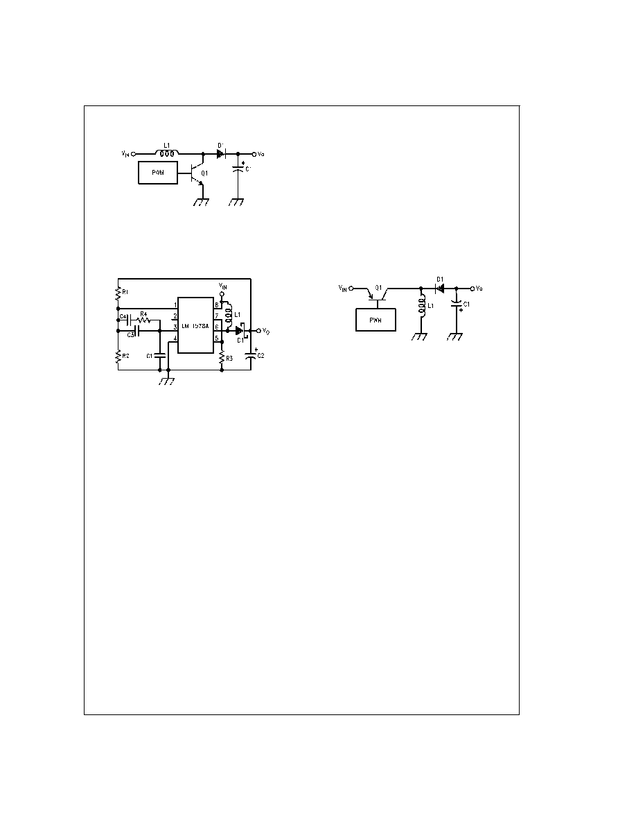
Typical Applications (Continued)
The circuit of
Figure 19 converts a 5V supply into a 15V sup-
ply with 150 mA of output current, a load regulation of 14 mV
(30 mA to 140 mA), and a line regulation of 35 mV (4.5V
≤
V
in ≤ 8.5V).
R1 = (V
o 1) R2 where R2 = 10 k.
R3 = V/(I
L(max, DC) + 0.5 IL)
where:
I
L = 2(ILOAD(min))(Vo/Vin)
I
L is 200 mA in this example.
R4, C3 and C4 are necessary for continuous operation and
are typically 220 k
, 20 pF, and 0.0022 F respectively.
C1 is the timing capacitor found in
Figure 1.
C2
≥ I
o (Vo Vin)/(fosc Vo Vripple).
D1 is a Schottky type diode such as a IN5818 or IN5819.
L1 is found as described in the buck converter section, using
the inductance chart for
Figure 16 for the boost configuration
and 20% discontinuity.
INVERTING REGULATOR
Figure 20 shows the basic configuration for an inverting
regulator. The input voltage is of a positive polarity, but the
output is negative. The output may be less than, equal to, or
greater in magnitude than the input. The relationship be-
tween the magnitude of the input voltage and the output volt-
age is V
o = Vin x(ton/toff).
Figure 21 shows an LM1578A configured as a 5V to 15V
polarity inverter with an output current of 300 mA, a load
regulation of 44 mV (60 mA to 300 mA) and a line regulation
of 50 mV (4.5V
≤ V
in ≤ 8.5V).
R1 = (|V
o| +1) R2 where R2 = 10 k.
R3 = V/(I
L(max, DC) + 0.5 IL).
R4 = 10V
BE1Bf/(IL (max, DC) + 0.5 IL)
where:
V, V
BE1,Vsat, and Bf are defined in the “Buck Converter with
Boosted Output Current” section.
I
L = 2(ILOAD(min))(Vin +|Vo|)/VIN
R5 is defined in the “Buck with Boosted Output Current” sec-
tion.
R6 serves the same purpose as R4 in the Boost Regulator
circuit and is typically 220 k
.
C1, C3 and C4 are defined in the “Boost Regulator” section.
C2
≥ I
o |Vo|/[fosc(|Vo|+Vin)Vripple]
L1 is found as outlined in the section on buck converters, us-
ing the inductance chart of
Figure 16 for the invert configura-
tion and 20% discontinuity.
DS008711-9
FIGURE 18. Basic Boost Regulator
DS008711-11
Vin = 5V
R4 = 200 k
Vo = 15V
C1 = 1820 pF
Vripple = 10 mV
C2 = 470 F
Io = 140 mA
C3 = 20 pF
fosc = 50 kHz
C4 = 0.0022 F
R1 = 140 k
L1 = 330 H
R2 = 10 k
D1 = 1N5818
R3 = 0.15
FIGURE 19. Boost or Step-Up Regulator
DS008711-10
FIGURE 20. Basic Inverting Regulator
13
www.national.com
相关PDF资料 |
PDF描述 |
|---|---|
| LM2586-5.0MDC | 7 A SWITCHING REGULATOR, 200 kHz SWITCHING FREQ-MAX, UUC |
| LM2586-5.0MWC | 7 A SWITCHING REGULATOR, 200 kHz SWITCHING FREQ-MAX, UUC |
| LM2586-ADJMDC | 7 A SWITCHING REGULATOR, 200 kHz SWITCHING FREQ-MAX, UUC |
| LM2586SX-12/NOPB | 3 A SWITCHING REGULATOR, 200 kHz SWITCHING FREQ-MAX, PSSO7 |
| LM2587SX-3.3/NOPB | 5 A SWITCHING REGULATOR, 100 kHz SWITCHING FREQ-MAX, PSSO5 |
相关代理商/技术参数 |
参数描述 |
|---|---|
| LM2581 | 制造商:NEC 功能描述:258 NEC'90 SMT TUBES N9F8A |
| LM258-1 | 制造商:NEC 功能描述:258 NEC'90 SMT TUBES N9F8A |
| LM2585S-12 | 功能描述:直流/直流开关转换器 RoHS:否 制造商:STMicroelectronics 最大输入电压:4.5 V 开关频率:1.5 MHz 输出电压:4.6 V 输出电流:250 mA 输出端数量:2 最大工作温度:+ 85 C 安装风格:SMD/SMT |
| LM2585S-12/NOPB | 功能描述:直流/直流开关转换器 RoHS:否 制造商:STMicroelectronics 最大输入电压:4.5 V 开关频率:1.5 MHz 输出电压:4.6 V 输出电流:250 mA 输出端数量:2 最大工作温度:+ 85 C 安装风格:SMD/SMT |
| LM2585S-3.3 | 功能描述:直流/直流开关转换器 RoHS:否 制造商:STMicroelectronics 最大输入电压:4.5 V 开关频率:1.5 MHz 输出电压:4.6 V 输出电流:250 mA 输出端数量:2 最大工作温度:+ 85 C 安装风格:SMD/SMT |
发布紧急采购,3分钟左右您将得到回复。