- 您现在的位置:买卖IC网 > PDF目录67755 > LM2585-5.0MDC (NATIONAL SEMICONDUCTOR CORP) 7 A SWITCHING REGULATOR, 125 kHz SWITCHING FREQ-MAX, UUC PDF资料下载
参数资料
| 型号: | LM2585-5.0MDC |
| 厂商: | NATIONAL SEMICONDUCTOR CORP |
| 元件分类: | 稳压器 |
| 英文描述: | 7 A SWITCHING REGULATOR, 125 kHz SWITCHING FREQ-MAX, UUC |
| 封装: | DIE |
| 文件页数: | 29/29页 |
| 文件大小: | 708K |
| 代理商: | LM2585-5.0MDC |
第1页第2页第3页第4页第5页第6页第7页第8页第9页第10页第11页第12页第13页第14页第15页第16页第17页第18页第19页第20页第21页第22页第23页第24页第25页第26页第27页第28页当前第29页
Flyback Regulator Operation
The LM2585 is ideally suited for use in the flyback regulator
topology. The flyback regulator can produce a single output
voltage, such as the one shown in
Figure 4, or multiple
output voltages. In
Figure 4, the flyback regulator generates
an output voltage that is inside the range of the input voltage.
This feature is unique to flyback regulators and cannot be
duplicated with buck or boost regulators.
The operation of a flyback regulator is as follows (refer to
Figure 4): when the switch is on, current flows through the
primary winding of the transformer, T1, storing energy in the
magnetic field of the transformer. Note that the primary and
secondary windings are out of phase, so no current flows
through the secondary when current flows through the pri-
mary. When the switch turns off, the magnetic field col-
lapses, reversing the voltage polarity of the primary and
secondary windings. Now rectifier D1 is forward biased and
current flows through it, releasing the energy stored in the
transformer. This produces voltage at the output.
The output voltage is controlled by modulating the peak
switch current. This is done by feeding back a portion of the
output voltage to the error amp, which amplifies the differ-
ence between the feedback voltage and a 1.230V reference.
The error amp output voltage is compared to a ramp voltage
proportional to the switch current (i.e., inductor current dur-
ing the switch on time). The comparator terminates the
switch on time when the two voltages are equal, thereby
controlling the peak switch current to maintain a constant
output voltage.
DS012515-21
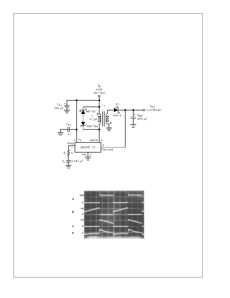
As shown in
Figure 4, the LM2585 can be used as a flyback regulator by using a minimum number of external components. The switching waveforms of this
regulator are shown in
Figure 5. Typical Performance Characteristics observed during the operation of this circuit are shown in Figure 6.
FIGURE 4. 12V Flyback Regulator Design Example
DS012515-22
A: Switch Voltage, 20 V/div
B: Switch Current, 2 A/div
C: Output Rectifier Current, 2 A/div
D: Output Ripple Voltage, 50 mV/div
AC-Coupled
Horizontal: 2 s/div
FIGURE 5. Switching Waveforms
LM2585
www.national.com
9
相关PDF资料 |
PDF描述 |
|---|---|
| LM2585-5.0MWC | 7 A SWITCHING REGULATOR, 125 kHz SWITCHING FREQ-MAX, UUC |
| LM2585-12MDC | 7 A SWITCHING REGULATOR, 125 kHz SWITCHING FREQ-MAX, UUC |
| LM2585-12MWC | 7 A SWITCHING REGULATOR, 125 kHz SWITCHING FREQ-MAX, UUC |
| LM2631MTC-ADJ/NOPB | SWITCHING CONTROLLER, 345 kHz SWITCHING FREQ-MAX, PDSO20 |
| LM2635M/NOPB | SWITCHING CONTROLLER, 350 kHz SWITCHING FREQ-MAX, PDSO20 |
相关代理商/技术参数 |
参数描述 |
|---|---|
| LM2585S-12 | 功能描述:直流/直流开关转换器 RoHS:否 制造商:STMicroelectronics 最大输入电压:4.5 V 开关频率:1.5 MHz 输出电压:4.6 V 输出电流:250 mA 输出端数量:2 最大工作温度:+ 85 C 安装风格:SMD/SMT |
| LM2585S-12/NOPB | 功能描述:直流/直流开关转换器 RoHS:否 制造商:STMicroelectronics 最大输入电压:4.5 V 开关频率:1.5 MHz 输出电压:4.6 V 输出电流:250 mA 输出端数量:2 最大工作温度:+ 85 C 安装风格:SMD/SMT |
| LM2585S-3.3 | 功能描述:直流/直流开关转换器 RoHS:否 制造商:STMicroelectronics 最大输入电压:4.5 V 开关频率:1.5 MHz 输出电压:4.6 V 输出电流:250 mA 输出端数量:2 最大工作温度:+ 85 C 安装风格:SMD/SMT |
| LM2585S-3.3/NOPB | 功能描述:直流/直流开关转换器 RoHS:否 制造商:STMicroelectronics 最大输入电压:4.5 V 开关频率:1.5 MHz 输出电压:4.6 V 输出电流:250 mA 输出端数量:2 最大工作温度:+ 85 C 安装风格:SMD/SMT |
| LM2585S-5.0 | 功能描述:直流/直流开关转换器 RoHS:否 制造商:STMicroelectronics 最大输入电压:4.5 V 开关频率:1.5 MHz 输出电压:4.6 V 输出电流:250 mA 输出端数量:2 最大工作温度:+ 85 C 安装风格:SMD/SMT |
发布紧急采购,3分钟左右您将得到回复。