- 您现在的位置:买卖IC网 > PDF目录44549 > LM2594-ADJMWC (NATIONAL SEMICONDUCTOR CORP) 1.4 A SWITCHING REGULATOR, 173 kHz SWITCHING FREQ-MAX, UUC PDF资料下载
参数资料
| 型号: | LM2594-ADJMWC |
| 厂商: | NATIONAL SEMICONDUCTOR CORP |
| 元件分类: | 稳压器 |
| 英文描述: | 1.4 A SWITCHING REGULATOR, 173 kHz SWITCHING FREQ-MAX, UUC |
| 封装: | WAFER |
| 文件页数: | 10/33页 |
| 文件大小: | 837K |
| 代理商: | LM2594-ADJMWC |
第1页第2页第3页第4页第5页第6页第7页第8页第9页当前第10页第11页第12页第13页第14页第15页第16页第17页第18页第19页第20页第21页第22页第23页第24页第25页第26页第27页第28页第29页第30页第31页第32页第33页
Application Information (Continued)
Feedback — Senses the regulated output voltage to com-
plete the feedback loop.
ON /OFF — Allows the switching regulator circuit to be shut
down using logic level signals thus dropping the total input
supply current to approximately 80 A. Pulling this pin below
a threshold voltage of approximately 1.3V turns the regulator
on, and pulling this pin above 1.3V (up to a maximum of 25V)
shuts the regulator down. If this shutdown feature is not
needed, the ON /OFF pin can be wired to the ground pin or
it can be left open, in either case the regulator will be in the
ON condition.
EXTERNAL COMPONENTS
C
IN — A low ESR aluminum or tantalum bypass capacitor is
needed between the input pin and ground pin. It must be lo-
cated near the regulator using short leads. This capacitor
prevents large voltage transients from appearing at the in-
put, and provides the instantaneous current needed each
time the switch turns on.
The important parameters for the Input capacitor are the
voltage rating and the RMS current rating. Because of the
relatively high RMS currents flowing in a buck regulator’s in-
put capacitor, this capacitor should be chosen for its RMS
current rating rather than its capacitance or voltage ratings,
although the capacitance value and voltage rating are di-
rectly related to the RMS current rating.
The RMS current rating of a capacitor could be viewed as a
capacitor’s power rating. The RMS current flowing through
the capacitors internal ESR produces power which causes
the internal temperature of the capacitor to rise. The RMS
current rating of a capacitor is determined by the amount of
current required to raise the internal temperature approxi-
mately 10C above an ambient temperature of 105C. The
ability of the capacitor to dissipate this heat to the surround-
ing air will determine the amount of current the capacitor can
safely sustain. Capacitors that are physically large and have
a large surface area will typically have higher RMS current
ratings. For a given capacitor value, a higher voltage electro-
lytic capacitor will be physically larger than a lower voltage
capacitor, and thus be able to dissipate more heat to the sur-
rounding air, and therefore will have a higher RMS current
rating.
The consequences of operating an electrolytic capacitor
above the RMS current rating is a shortened operating life.
The higher temperature speeds up the evaporation of the ca-
pacitor’s electrolyte, resulting in eventual failure.
Selecting an input capacitor requires consulting the manu-
facturers data sheet for maximum allowable RMS ripple cur-
rent. For a maximum ambient temperature of 40C, a gen-
eral guideline would be to select a capacitor with a ripple
current rating of approximately 50% of the DC load current.
For ambient temperatures up to 70C, a current rating of
75% of the DC load current would be a good choice for a
conservative design. The capacitor voltage rating must be at
least 1.25 times greater than the maximum input voltage,
and often a much higher voltage capacitor is needed to sat-
isfy the RMS current requirements.
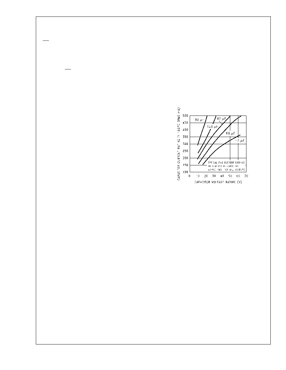
A graph shown in
Figure 13 shows the relationship between
an electrolytic capacitor value, its voltage rating, and the
RMS current it is rated for. These curves were obtained from
the Nichicon “PL” series of low ESR, high reliability electro-
lytic capacitors designed for switching regulator applications.
Other capacitor manufacturers offer similar types of capaci-
tors, but always check the capacitor data sheet.
“Standard” electrolytic capacitors typically have much higher
ESR numbers, lower RMS current ratings and typically have
a shorter operating lifetime.
Because of their small size and excellent performance, sur-
face mount solid tantalum capacitors are often used for input
bypassing, but several precautions must be observed. A
small percentage of solid tantalum capacitors can short if the
inrush current rating is exceeded. This can happen at turn on
when the input voltage is suddenly applied, and of course,
higher input voltages produce higher inrush currents. Sev-
eral capacitor manufacturers do a 100% surge current test-
ing on their products to minimize this potential problem. If
high turn on currents are expected, it may be necessary to
limit this current by adding either some resistance or induc-
tance before the tantalum capacitor, or select a higher volt-
age capacitor. As with aluminum electrolytic capacitors, the
RMS ripple current rating must be sized to the load current.
OUTPUT CAPACITOR
C
OUT — An output capacitor is required to filter the output
and provide regulator loop stability. Low impedance or low
ESR Electrolytic or solid tantalum capacitors designed for
switching regulator applications must be used. When select-
ing an output capacitor, the important capacitor parameters
are; the 100 kHz Equivalent Series Resistance (ESR), the
RMS ripple current rating, voltage rating, and capacitance
value. For the output capacitor, the ESR value is the most
important parameter.
The output capacitor requires an ESR value that has an up-
per and lower limit. For low output ripple voltage, a low ESR
value is needed. This value is determined by the maximum
allowable output ripple voltage, typically 1% to 2% of the out-
put voltage. But if the selected capacitor’s ESR is extremely
low, there is a possibility of an unstable feedback loop, re-
sulting in an oscillation at the output. Using the capacitors
listed in the tables, or similar types, will provide design solu-
tions under all conditions.
If very low output ripple voltage (less than 15 mV) is re-
quired, refer to the section on Output Voltage Ripple and
Transients for a post ripple filter.
An aluminum electrolytic capacitor’s ESR value is related to
the capacitance value and its voltage rating. In most cases,
Higher voltage electrolytic capacitors have lower ESR values
DS012439-28
FIGURE 13. RMS Current Ratings for Low ESR
Electrolytic Capacitors (Typical)
LM2594/LM2594HV
www.national.com
18
相关PDF资料 |
PDF描述 |
|---|---|
| LM2594HV-12MWC | 1.4 A SWITCHING REGULATOR, 173 kHz SWITCHING FREQ-MAX, UUC |
| LM2594HV-12MDC | 1.4 A SWITCHING REGULATOR, 173 kHz SWITCHING FREQ-MAX, UUC |
| LM2594-3.3MDC | 1.4 A SWITCHING REGULATOR, 173 kHz SWITCHING FREQ-MAX, UUC |
| LM2595J-12-QML | 2.6 A SWITCHING REGULATOR, 173 kHz SWITCHING FREQ-MAX, CDIP16 |
| 5962-9687901QEA | 2.6 A SWITCHING REGULATOR, 173 kHz SWITCHING FREQ-MAX, CDIP16 |
相关代理商/技术参数 |
参数描述 |
|---|---|
| LM2594APDBCKGEVB | 功能描述:电源管理IC开发工具 LM2594ADJ PDIP8 BUCK DB RoHS:否 制造商:Maxim Integrated 产品:Evaluation Kits 类型:Battery Management 工具用于评估:MAX17710GB 输入电压: 输出电压:1.8 V |
| LM2594ASCBCKGEVB | 功能描述:BOARD EVAL FOR LM2594ADJ 8-SOIC RoHS:是 类别:编程器,开发系统 >> 评估板 - DC/DC 与 AC/DC(离线)SMPS 系列:* 产品培训模块:Obsolescence Mitigation Program 标准包装:1 系列:True Shutdown™ 主要目的:DC/DC,步升 输出及类型:1,非隔离 功率 - 输出:- 输出电压:- 电流 - 输出:1A 输入电压:2.5 V ~ 5.5 V 稳压器拓扑结构:升压 频率 - 开关:3MHz 板类型:完全填充 已供物品:板 已用 IC / 零件:MAX8969 |
| LM2594DADJG | 功能描述:直流/直流开关调节器 0.5A BUCK SW REG 150KHZ RoHS:否 制造商:International Rectifier 最大输入电压:21 V 开关频率:1.5 MHz 输出电压:0.5 V to 0.86 V 输出电流:4 A 输出端数量: 最大工作温度: 安装风格:SMD/SMT 封装 / 箱体:PQFN 4 x 5 |
| LM2594DADJR2G | 功能描述:直流/直流开关调节器 0.5A BUCK SW REG 150KHZ RoHS:否 制造商:International Rectifier 最大输入电压:21 V 开关频率:1.5 MHz 输出电压:0.5 V to 0.86 V 输出电流:4 A 输出端数量: 最大工作温度: 安装风格:SMD/SMT 封装 / 箱体:PQFN 4 x 5 |
| LM2594HVM-12 | 功能描述:直流/直流开关转换器 RoHS:否 制造商:STMicroelectronics 最大输入电压:4.5 V 开关频率:1.5 MHz 输出电压:4.6 V 输出电流:250 mA 输出端数量:2 最大工作温度:+ 85 C 安装风格:SMD/SMT |
发布紧急采购,3分钟左右您将得到回复。