- 您现在的位置:买卖IC网 > PDF目录44549 > LM2594HV-12MWC (NATIONAL SEMICONDUCTOR CORP) 1.4 A SWITCHING REGULATOR, 173 kHz SWITCHING FREQ-MAX, UUC PDF资料下载
参数资料
| 型号: | LM2594HV-12MWC |
| 厂商: | NATIONAL SEMICONDUCTOR CORP |
| 元件分类: | 稳压器 |
| 英文描述: | 1.4 A SWITCHING REGULATOR, 173 kHz SWITCHING FREQ-MAX, UUC |
| 封装: | WAFER |
| 文件页数: | 15/33页 |
| 文件大小: | 837K |
| 代理商: | LM2594HV-12MWC |
第1页第2页第3页第4页第5页第6页第7页第8页第9页第10页第11页第12页第13页第14页当前第15页第16页第17页第18页第19页第20页第21页第22页第23页第24页第25页第26页第27页第28页第29页第30页第31页第32页第33页
Application Information (Continued)
These magnetic lines of flux will induce a voltage into any
wire or PC board copper trace that comes within the induc-
tor’s magnetic field. The strength of the magnetic field, the
orientation and location of the PC copper trace to the mag-
netic field, and the distance between the copper trace and
the inductor, determine the amount of voltage generated in
the copper trace. Another way of looking at this inductive
coupling is to consider the PC board copper trace as one
turn of a transformer (secondary) with the inductor winding
as the primary. Many millivolts can be generated in a copper
trace located near an open core inductor which can cause
stability problems or high output ripple voltage problems.
If unstable operation is seen, and an open core inductor is
used, it’s possible that the location of the inductor with re-
spect to other PC traces may be the problem. To determine
if this is the problem, temporarily raise the inductor away
from the board by several inches and then check circuit op-
eration. If the circuit now operates correctly, then the mag-
netic flux from the open core inductor is causing the problem.
Substituting a closed core inductor such as a torroid or
E-core will correct the problem, or re-arranging the PC layout
may be necessary. Magnetic flux cutting the IC device
ground trace, feedback trace, or the positive or negative
traces of the output capacitor should be minimized.
Sometimes, locating a trace directly beneath a bobbin in-
ductor will provide good results, provided it is exactly in the
center of the inductor (because the induced voltages cancel
themselves out), but if it is off center one direction or the
other, then problems could arise. If flux problems are
present, even the direction of the inductor winding can make
a difference in some circuits.
This discussion on open core inductors is not to frighten the
user, but to alert the user on what kind of problems to watch
out for when using them. Open core bobbin or “stick” induc-
tors are an inexpensive, simple way of making a compact ef-
ficient inductor, and they are used by the millions in many dif-
ferent applications.
THERMAL CONSIDERATIONS
The LM2594/LM2594HV is available in two packages, an
8-pin through hole DIP (N) and an 8-pin surface mount SO-8
(M). Both packages are molded plastic with a copper lead
frame. When the package is soldered to the PC board, the
copper and the board are the heat sink for the LM2594 and
the other heat producing components.
For best thermal performance, wide copper traces should be
used and all ground and unused pins should be soldered to
generous amounts of printed circuit board copper, such as a
ground plane (one exception to this is the output (switch) pin,
which should not have large areas of copper). Large areas of
copper provide the best transfer of heat (lower thermal resis-
tance) to the surrounding air, and even double-sided or mul-
tilayer boards provide a better heat path to the surrounding
air. Unless power levels are small, sockets are not recom-
mended because of the added thermal resistance it adds
and the resultant higher junction temperatures.
Package thermal resistance and junction temperature rise
numbers are all approximate, and there are many factors
that will affect the junction temperature. Some of these fac-
tors include board size, shape, thickness, position, location,
and even board temperature. Other factors are, trace width,
printed circuit copper area, copper thickness, single- or
double-sided, multilayer board, and the amount of solder on
the board. The effectiveness of the PC board to dissipate
heat also depends on the size, quantity and spacing of other
components on the board. Furthermore, some of these com-
ponents such as the catch diode will add heat to the PC
board and the heat can vary as the input voltage changes.
For the inductor, depending on the physical size, type of core
material and the DC resistance, it could either act as a heat
sink taking heat away from the board, or it could add heat to
the board.
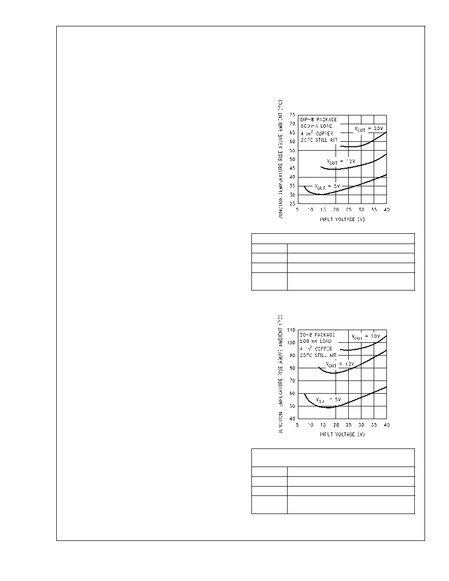
DS012439-35
Circuit Data for Temperature Rise Curve (DIP-8)
Capacitors
Through hole electrolytic
Inductor
Through hole, Schott, 100 H
Diode
Through hole, 1A 40V, Schottky
PC board
4 square inches single sided 2 oz. copper
(0.0028")
FIGURE 19. Junction Temperature Rise, DIP-8
DS012439-34
Circuit Data for Temperature Rise Curve
(Surface Mount)
Capacitors
Surface mount tantalum, molded “D” size
Inductor
Surface mount, Coilcraft DO33, 100 H
Diode
Surface mount, 1A 40V, Schottky
PC board
4 square inches single sided 2 oz. copper
(0.0028")
FIGURE 20. Junction Temperature Rise, SO-8
LM2594/LM2594HV
www.national.com
22
相关PDF资料 |
PDF描述 |
|---|---|
| LM2594HV-12MDC | 1.4 A SWITCHING REGULATOR, 173 kHz SWITCHING FREQ-MAX, UUC |
| LM2594-3.3MDC | 1.4 A SWITCHING REGULATOR, 173 kHz SWITCHING FREQ-MAX, UUC |
| LM2595J-12-QML | 2.6 A SWITCHING REGULATOR, 173 kHz SWITCHING FREQ-MAX, CDIP16 |
| 5962-9687901QEA | 2.6 A SWITCHING REGULATOR, 173 kHz SWITCHING FREQ-MAX, CDIP16 |
| 5962-9650301QEA | 2.6 A SWITCHING REGULATOR, 173 kHz SWITCHING FREQ-MAX, CDIP16 |
相关代理商/技术参数 |
参数描述 |
|---|---|
| LM2594HVM-12 | 功能描述:直流/直流开关转换器 RoHS:否 制造商:STMicroelectronics 最大输入电压:4.5 V 开关频率:1.5 MHz 输出电压:4.6 V 输出电流:250 mA 输出端数量:2 最大工作温度:+ 85 C 安装风格:SMD/SMT |
| LM2594HVM-12/NOPB | 功能描述:直流/直流开关转换器 150KHZ 0.5A STEP- DOWN VLTG REG RoHS:否 制造商:STMicroelectronics 最大输入电压:4.5 V 开关频率:1.5 MHz 输出电压:4.6 V 输出电流:250 mA 输出端数量:2 最大工作温度:+ 85 C 安装风格:SMD/SMT |
| LM2594HVM-12/NOPB | 制造商:Texas Instruments 功能描述:DC/DC Converter (DC-DC) / Switching Regu |
| LM2594HVM-3.3 | 功能描述:直流/直流开关转换器 RoHS:否 制造商:STMicroelectronics 最大输入电压:4.5 V 开关频率:1.5 MHz 输出电压:4.6 V 输出电流:250 mA 输出端数量:2 最大工作温度:+ 85 C 安装风格:SMD/SMT |
| LM2594HVM-3.3/NOPB | 功能描述:直流/直流开关转换器 150KHZ 0.5A STEP- DOWN VLTG REG RoHS:否 制造商:STMicroelectronics 最大输入电压:4.5 V 开关频率:1.5 MHz 输出电压:4.6 V 输出电流:250 mA 输出端数量:2 最大工作温度:+ 85 C 安装风格:SMD/SMT |
发布紧急采购,3分钟左右您将得到回复。