- 您现在的位置:买卖IC网 > PDF目录44549 > LM2595J-12-QML (NATIONAL SEMICONDUCTOR CORP) 2.6 A SWITCHING REGULATOR, 173 kHz SWITCHING FREQ-MAX, CDIP16 PDF资料下载
参数资料
| 型号: | LM2595J-12-QML |
| 厂商: | NATIONAL SEMICONDUCTOR CORP |
| 元件分类: | 稳压器 |
| 英文描述: | 2.6 A SWITCHING REGULATOR, 173 kHz SWITCHING FREQ-MAX, CDIP16 |
| 封装: | CERAMIC, DIP-16 |
| 文件页数: | 11/33页 |
| 文件大小: | 1016K |
| 代理商: | LM2595J-12-QML |
第1页第2页第3页第4页第5页第6页第7页第8页第9页第10页当前第11页第12页第13页第14页第15页第16页第17页第18页第19页第20页第21页第22页第23页第24页第25页第26页第27页第28页第29页第30页第31页第32页第33页
Application Information (Continued)
INDUCTOR SELECTION
All switching regulators have two basic modes of operation;
continuous and discontinuous. The difference between the
two types relates to the inductor current, whether it is flowing
continuously, or if it drops to zero for a period of time in the
normal switching cycle. Each mode has distinctively different
operating characteristics, which can affect the regulators
performance and requirements. Most switcher designs will
operate in the discontinuous mode when the load current is
low.
The LM2595 (or any of the Simple Switcher family) can be
used for both continuous or discontinuous modes of opera-
tion.
In many cases the preferred mode of operation is the con-
tinuous mode. It offers greater output power, lower peak
switch, inductor and diode currents, and can have lower out-
put ripple voltage. But it does require larger inductor values
to keep the inductor current flowing continuously, especially
at low output load currents and/or high input voltages.
To simplify the inductor selection process, an inductor selec-
tion guide (nomograph) was designed (see
Figure 4 through
Figure 7). This guide assumes that the regulator is operating
in the continuous mode, and selects an inductor that will al-
low a peak-to-peak inductor ripple current to be a certain
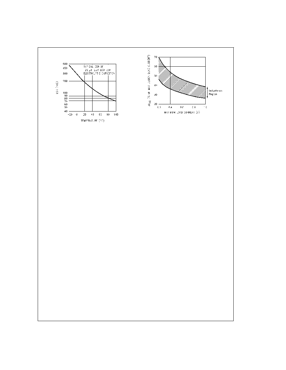
percentage of the maximum design load current. This
peak-to-peak inductor ripple current percentage is not fixed,
but is allowed to change as different design load currents are
selected. (See
Figure 16.)
By allowing the percentage of inductor ripple current to in-
crease for low load currents, the inductor value and size can
be kept relatively low.
When operating in the continuous mode, the inductor current
waveform ranges from a triangular to a sawtooth type of
waveform (depending on the input voltage), with the average
value of this current waveform equal to the DC output load
current.
Inductors are available in different styles such as pot core,
toroid, E-core, bobbin core, etc., as well as different core ma-
terials, such as ferrites and powdered iron. The least expen-
sive, the bobbin, rod or stick core, consists of wire wound on
a ferrite bobbin. This type of construction makes for an inex-
pensive inductor, but since the magnetic flux is not com-
pletely contained within the core, it generates more
Electro-Magnetic Interference (EMl). This magnetic flux can
induce voltages into nearby printed circuit traces, thus caus-
ing problems with both the switching regulator operation and
nearby sensitive circuitry, and can give incorrect scope read-
ings because of induced voltages in the scope probe. Also
see section on Open Core Inductors.
When multiple switching regulators are located on the same
PC board, open core magnetics can cause interference be-
tween two or more of the regulator circuits, especially at high
currents. A toroid or E-core inductor (closed magnetic struc-
ture) should be used in these situations.
The inductors listed in the selection chart include ferrite
E-core construction for Schott, ferrite bobbin core for Renco
and Coilcraft, and powdered iron toroid for Pulse Engineer-
ing.
Exceeding an inductor’s maximum current rating may cause
the inductor to overheat because of the copper wire losses,
or the core may saturate. If the inductor begins to saturate,
the inductance decreases rapidly and the inductor begins to
look mainly resistive (the DC resistance of the winding). This
can cause the switch current to rise very rapidly and force
the switch into a cycle-by-cycle current limit, thus reducing
the DC output load current. This can also result in overheat-
ing of the inductor and/or the LM2595. Different inductor
types have different saturation characteristics, and this
should be kept in mind when selecting an inductor.
The inductor manufacturer’s data sheets include current and
energy limits to avoid inductor saturation.
DS012565-30
FIGURE 15. Capacitor ESR Change vs Temperature
DS012565-31
FIGURE 16. (
I
IND) Peak-to-Peak
Inductor Ripple Current (as a Percentage
of the Load Current) vs Load Current
www.national.com
19
相关PDF资料 |
PDF描述 |
|---|---|
| 5962-9687901QEA | 2.6 A SWITCHING REGULATOR, 173 kHz SWITCHING FREQ-MAX, CDIP16 |
| 5962-9650301QEA | 2.6 A SWITCHING REGULATOR, 173 kHz SWITCHING FREQ-MAX, CDIP16 |
| 5962-9650401QEA | 2.6 A SWITCHING REGULATOR, 173 kHz SWITCHING FREQ-MAX, CDIP16 |
| LM2595J-3.3-QML | 2.6 A SWITCHING REGULATOR, 173 kHz SWITCHING FREQ-MAX, CDIP16 |
| LM2595-5.0MDC | 2.6 A SWITCHING REGULATOR, 173 kHz SWITCHING FREQ-MAX, UUC |
相关代理商/技术参数 |
参数描述 |
|---|---|
| LM2595S12 | 制造商:Texas Instruments 功能描述:SWITCHING REG, 1A 12V, SMD, 2595 制造商:Texas Instruments 功能描述:SWITCHING REG, 1A 12V, SMD, 2595; Primary Input Voltage:24V; No. of Outputs:1; Output Voltage:12V; Output Current:1A; Voltage Regulator Case Style:TO-263; No. of Pins:5; Operating Temperature Min:-25C; Operating Temperature ;RoHS Compliant: Yes |
| LM2595S-12 | 功能描述:直流/直流开关转换器 RoHS:否 制造商:STMicroelectronics 最大输入电压:4.5 V 开关频率:1.5 MHz 输出电压:4.6 V 输出电流:250 mA 输出端数量:2 最大工作温度:+ 85 C 安装风格:SMD/SMT |
| LM2595S12 | 制造商:Texas Instruments 功能描述:IC SWITCHING REG 1A 12V SMD 2595 |
| LM2595S-12/NOPB | 功能描述:直流/直流开关转换器 RoHS:否 制造商:STMicroelectronics 最大输入电压:4.5 V 开关频率:1.5 MHz 输出电压:4.6 V 输出电流:250 mA 输出端数量:2 最大工作温度:+ 85 C 安装风格:SMD/SMT |
| LM2595S-3.3 | 功能描述:直流/直流开关转换器 RoHS:否 制造商:STMicroelectronics 最大输入电压:4.5 V 开关频率:1.5 MHz 输出电压:4.6 V 输出电流:250 mA 输出端数量:2 最大工作温度:+ 85 C 安装风格:SMD/SMT |
发布紧急采购,3分钟左右您将得到回复。