- 您现在的位置:买卖IC网 > PDF目录44549 > LM2599-3.3MWC (NATIONAL SEMICONDUCTOR CORP) 7.5 A SWITCHING REGULATOR, 173 kHz SWITCHING FREQ-MAX, UUC PDF资料下载
参数资料
| 型号: | LM2599-3.3MWC |
| 厂商: | NATIONAL SEMICONDUCTOR CORP |
| 元件分类: | 稳压器 |
| 英文描述: | 7.5 A SWITCHING REGULATOR, 173 kHz SWITCHING FREQ-MAX, UUC |
| 封装: | WAFER |
| 文件页数: | 13/36页 |
| 文件大小: | 897K |
| 代理商: | LM2599-3.3MWC |
第1页第2页第3页第4页第5页第6页第7页第8页第9页第10页第11页第12页当前第13页第14页第15页第16页第17页第18页第19页第20页第21页第22页第23页第24页第25页第26页第27页第28页第29页第30页第31页第32页第33页第34页第35页第36页
Application Information (Continued)
DELAY CAPACITOR
C
DELAY — Provides delay for the error flag output. See the
upper curve in
Figure 13, and also refer to timing diagrams in
Figure 14. A capacitor on this pin provides a time delay
between the time the regulated output voltage (when it is
increasing in value) reaches 95% of the nominal output
voltage, and the time the error flag output goes high. A 3 A
constant current from the delay pin charges the delay ca-
pacitor resulting in a voltage ramp. When this voltage
reaches a threshold of approximately 1.3V, the open collec-
tor error flag output (or power OK) goes high. This signal can
be used to indicate that the regulated output has reached the
correct voltage and has stabilized.
If, for any reason, the regulated output voltage drops by 5%
or more, the error output flag (Pin 3) immediately goes low
(internal transistor turns on). The delay capacitor provides
very little delay if the regulated output is dropping out of
regulation. The delay time for an output that is decreasing is
approximately a 1000 times less than the delay for the rising
output. For a 0.1 F delay capacitor, the delay time would be
approximately 50 ms when the output is rising and passes
through the 95% threshold, but the delay for the output
dropping would only be approximately 50 s.
R
Pull Up — The error flag output, (or power OK) is the col-
lector of a NPN transistor, with the emitter internally
grounded. To use the error flag, a pullup resistor to a positive
voltage is needed. The error flag transistor is rated up to a
maximum of 45V and can sink approximately 3 mA. If the
error flag is not used, it can be left open.
FEEDFORWARD CAPACITOR
(Adjustable Output Voltage Version)
C
FF - A Feedforward Capacitor CFF, shown across R2 in
Figure 1 is used when the output voltage is greater than 10V
or when C
OUT has a very low ESR. This capacitor adds lead
compensation to the feedback loop and increases the phase
margin for better loop stability. For C
FF selection, see the
design procedure section.
If the output ripple is large (> 5% of the nominal output
voltage), this ripple can be coupled to the feedback pin
through the feedforward capacitor and cause the error com-
parator to trigger the error flag. In this situation, adding a
resistor, R
FF, in series with the feedforward capacitor, ap-
proximately 3 times R1, will attenuate the ripple voltage at
the feedback pin.
INPUT CAPACITOR
C
IN — A low ESR aluminum or tantalum bypass capacitor is
needed between the input pin and ground pin. It must be
located near the regulator using short leads. This capacitor
prevents large voltage transients from appearing at the in-
put, and provides the instantaneous current needed each
time the switch turns on.
The important parameters for the Input capacitor are the
voltage rating and the RMS current rating. Because of the
relatively high RMS currents flowing in a buck regulator’s
input capacitor, this capacitor should be chosen for its RMS
current rating rather than its capacitance or voltage ratings,
although the capacitance value and voltage rating are di-
rectly related to the RMS current rating.
The RMS current rating of a capacitor could be viewed as a
capacitor’s power rating. The RMS current flowing through
the capacitors internal ESR produces power which causes
the internal temperature of the capacitor to rise. The RMS
current rating of a capacitor is determined by the amount of
current required to raise the internal temperature approxi-
mately 10C above an ambient temperature of 105C. The
ability of the capacitor to dissipate this heat to the surround-
ing air will determine the amount of current the capacitor can
safely sustain. Capacitors that are physically large and have
a large surface area will typically have higher RMS current
ratings. For a given capacitor value, a higher voltage elec-
trolytic capacitor will be physically larger than a lower voltage
capacitor, and thus be able to dissipate more heat to the
surrounding air, and therefore will have a higher RMS cur-
rent rating.
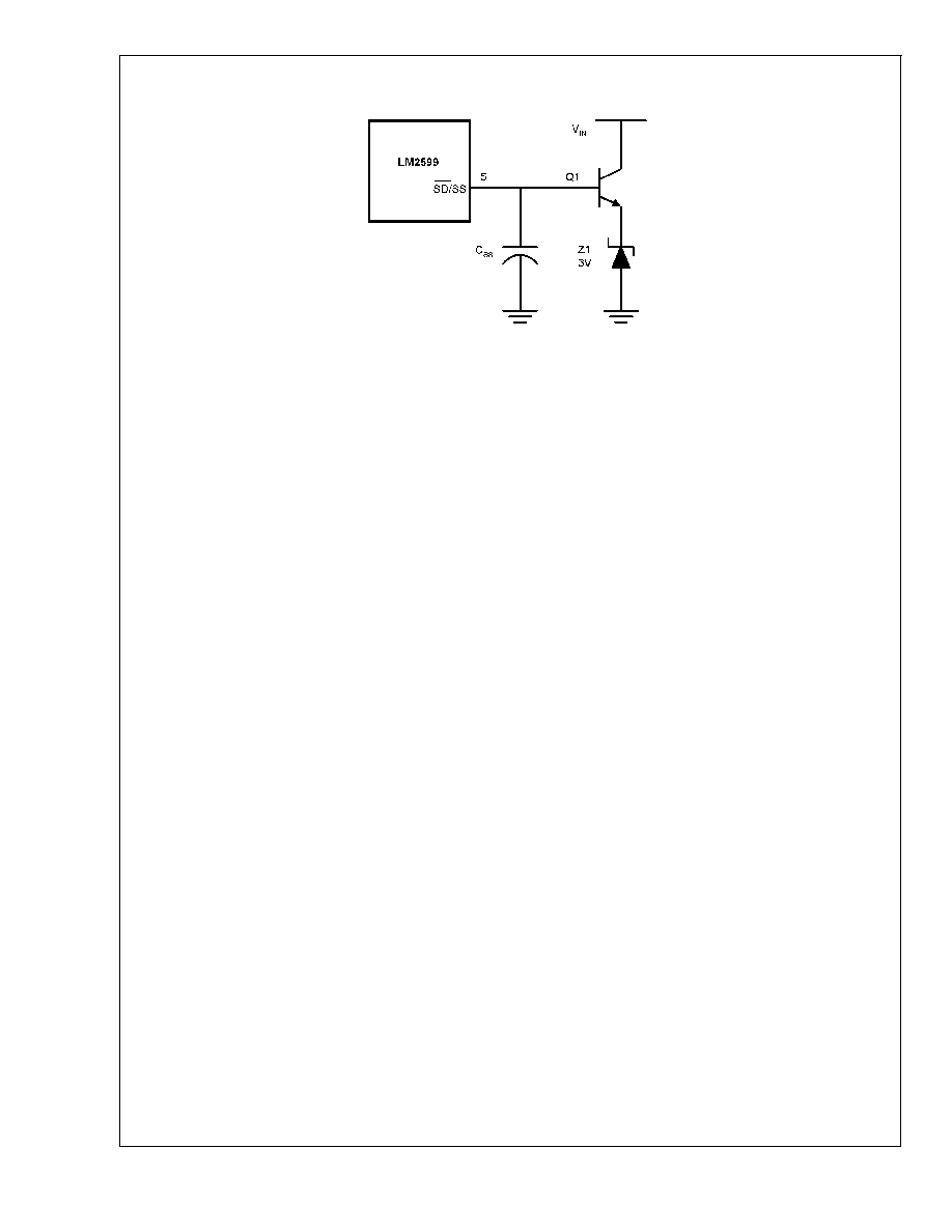
DS012582-65
FIGURE 15. External 3.7V Soft-Start Clamp
LM2599
www.national.com
20
相关PDF资料 |
PDF描述 |
|---|---|
| LM2621MDC | 2.85 A SWITCHING REGULATOR, 2000 kHz SWITCHING FREQ-MAX, UUC |
| LM2622-ADJMWC | 2.3 A SWITCHING REGULATOR, 1500 kHz SWITCHING FREQ-MAX, UUC |
| LM2630MTC-ADJ/NOPB | SWITCHING CONTROLLER, 345 kHz SWITCHING FREQ-MAX, PDSO20 |
| LM2630MTC-ADJX | SWITCHING CONTROLLER, 345 kHz SWITCHING FREQ-MAX, PDSO20 |
| LM2631MTCX-ADJ/NOPB | SWITCHING CONTROLLER, 400 kHz SWITCHING FREQ-MAX, PDSO20 |
相关代理商/技术参数 |
参数描述 |
|---|---|
| LM2599S-12 | 功能描述:直流/直流开关转换器 RoHS:否 制造商:STMicroelectronics 最大输入电压:4.5 V 开关频率:1.5 MHz 输出电压:4.6 V 输出电流:250 mA 输出端数量:2 最大工作温度:+ 85 C 安装风格:SMD/SMT |
| LM2599S-12/NOPB | 功能描述:直流/直流开关转换器 RoHS:否 制造商:STMicroelectronics 最大输入电压:4.5 V 开关频率:1.5 MHz 输出电压:4.6 V 输出电流:250 mA 输出端数量:2 最大工作温度:+ 85 C 安装风格:SMD/SMT |
| LM2599S-3.3 | 功能描述:直流/直流开关转换器 RoHS:否 制造商:STMicroelectronics 最大输入电压:4.5 V 开关频率:1.5 MHz 输出电压:4.6 V 输出电流:250 mA 输出端数量:2 最大工作温度:+ 85 C 安装风格:SMD/SMT |
| LM2599S-3.3/NOPB | 功能描述:直流/直流开关转换器 RoHS:否 制造商:STMicroelectronics 最大输入电压:4.5 V 开关频率:1.5 MHz 输出电压:4.6 V 输出电流:250 mA 输出端数量:2 最大工作温度:+ 85 C 安装风格:SMD/SMT |
| LM2599S-5.0 | 功能描述:直流/直流开关转换器 RoHS:否 制造商:STMicroelectronics 最大输入电压:4.5 V 开关频率:1.5 MHz 输出电压:4.6 V 输出电流:250 mA 输出端数量:2 最大工作温度:+ 85 C 安装风格:SMD/SMT |
发布紧急采购,3分钟左右您将得到回复。