- 您现在的位置:买卖IC网 > PDF目录44549 > LM2599-ADJMWC (NATIONAL SEMICONDUCTOR CORP) 7.5 A SWITCHING REGULATOR, 173 kHz SWITCHING FREQ-MAX, UUC PDF资料下载
参数资料
| 型号: | LM2599-ADJMWC |
| 厂商: | NATIONAL SEMICONDUCTOR CORP |
| 元件分类: | 稳压器 |
| 英文描述: | 7.5 A SWITCHING REGULATOR, 173 kHz SWITCHING FREQ-MAX, UUC |
| 封装: | WAFER |
| 文件页数: | 5/36页 |
| 文件大小: | 897K |
| 代理商: | LM2599-ADJMWC |
第1页第2页第3页第4页当前第5页第6页第7页第8页第9页第10页第11页第12页第13页第14页第15页第16页第17页第18页第19页第20页第21页第22页第23页第24页第25页第26页第27页第28页第29页第30页第31页第32页第33页第34页第35页第36页
LM2599 Series Buck Regulator Design Procedure (Adjustable Output)
(Continued)
PROCEDURE (Adjustable Output Voltage Version)
EXAMPLE (Adjustable Output Voltage Version)
2. Inductor Selection (L1)
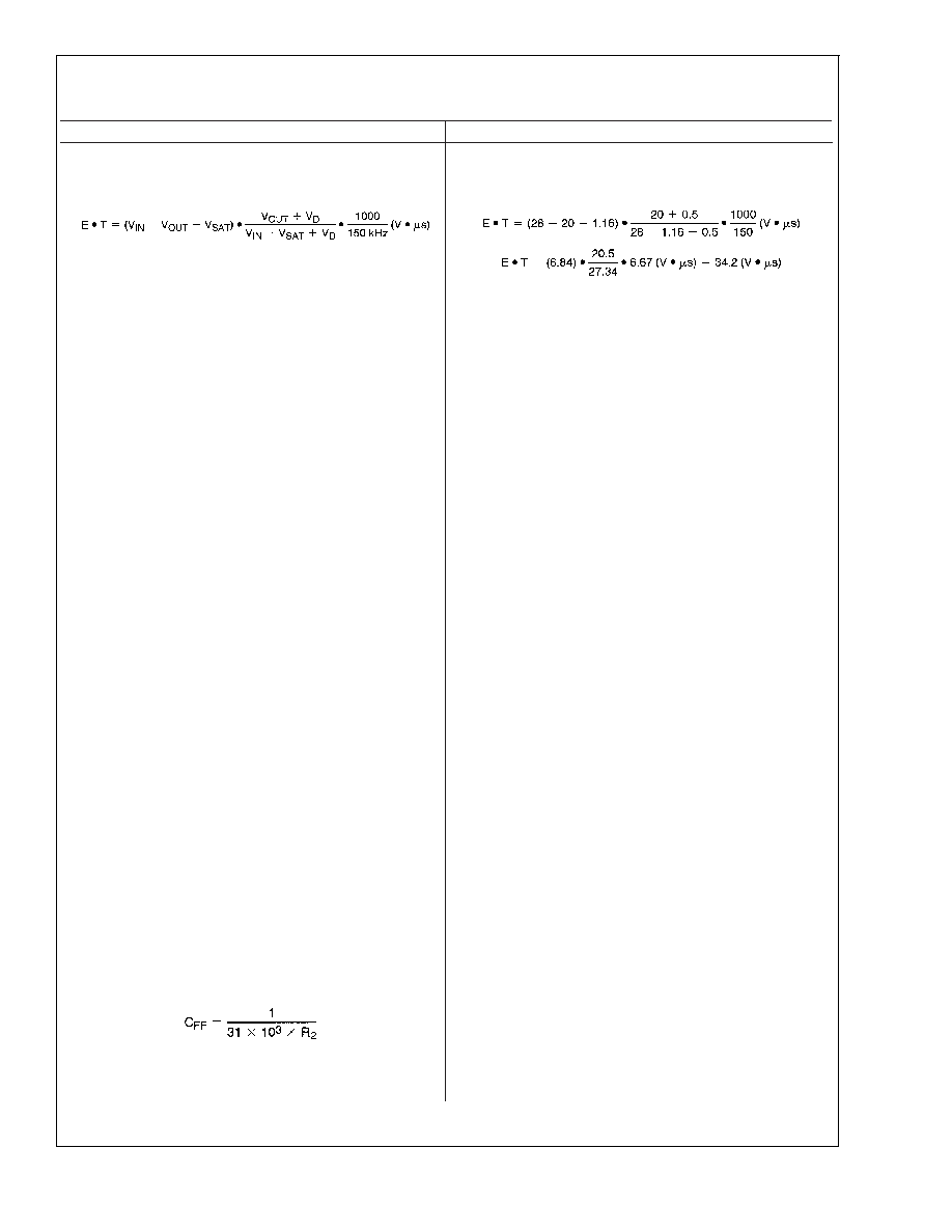
A. Calculate the inductor Volt
microsecond constant E T
(V
s), from the following formula:
where V
SAT = internal switch saturation voltage = 1.16V and
V
D = diode forward voltage drop = 0.5V
B. Use the E
T value from the previous formula and match
it with the E
T number on the vertical axis of the Inductor
Value Selection Guide shown in
Figure 7.
C. on the horizontal axis, select the maximum load current.
D. Identify the inductance region intersected by the E
T
value and the Maximum Load Current value. Each region is
identified by an inductance value and an inductor code
(LXX).
E. Select an appropriate inductor from the four manufactur-
er’s part numbers listed in
Figure 8.
2. Inductor Selection (L1)
A. Calculate the inductor Volt
microsecond constant (E
T),
B. E
T = 34.2 (V s)
C. I
LOAD(max) = 3A
D. From the inductor value selection guide shown in
Figure 7,
the inductance region intersected by the 34 (V
s) horizon-
tal line and the 3A vertical line is 47 H, and the inductor
code is L39.
E. From the table in
Figure 8, locate line L39, and select an
inductor part number from the list of manufacturers part
numbers.
3. Output Capacitor Selection (C
OUT)
A. In the majority of applications, low ESR electrolytic or solid
tantalum capacitors between 82 F and 820 F provide the
best results. This capacitor should be located close to the IC
using short capacitor leads and short copper traces. Do not
use capacitors larger than 820 F. For additional informa-
tion, see section on output capacitors in application
information section.
B. To simplify the capacitor selection procedure, refer to the
quick design table shown in
Figure 3. This table contains
different output voltages, and lists various output capacitors
that will provide the best design solutions.
C. The capacitor voltage rating should be at least 1.5 times
greater than the output voltage, and often much higher volt-
age ratings are needed to satisfy the low ESR requirements
needed for low output ripple voltage.
3. Output Capacitor SeIection (C
OUT)
A. See section on C
OUT in Application Information section.
B. From the quick design table shown in
Figure 3, locate the
output voltage column. From that column, locate the output
voltage closest to the output voltage in your application. In
this example, select the 24V line. Under the output capacitor
section, select a capacitor from the list of through hole elec-
trolytic or surface mount tantalum types from four different
capacitor manufacturers. It is recommended that both the
manufacturers and the manufacturers series that are listed in
the table be used.
In this example, through hole aluminum electrolytic capaci-
tors from several different manufacturers are available.
220/35 Panasonic HFQ Series
150/35 Nichicon PL Series
C. For a 20V output, a capacitor rating of at least 30V or
more is needed. In this example, either a 35V or 50V capaci-
tor would work. A 50V rating was chosen because it has a
lower ESR which provides a lower output ripple voltage.
Other manufacturers or other types of capacitors may also
be used, provided the capacitor specifications (especially the
100 kHz ESR) closely match the types listed in the table.
Refer to the capacitor manufacturers data sheet for this
information.
4. Feedforward Capacitor (C
FF) (See Figure 1)
For output voltages greater than approximately 10V, an ad-
ditional capacitor is required. The compensation capacitor is
typically between 100 pF and 33 nF, and is wired in parallel
with the output voltage setting resistor, R
2. It provides addi-
tional stability for high output voltages, low input-output volt-
ages, and/or very low ESR output capacitors, such as solid
tantalum capacitors.
This capacitor type can be ceramic, plastic, silver mica, etc.
(Because of the unstable characteristics of ceramic capaci-
tors made with Z5U material, they are not recommended.)
4. Feedforward Capacitor (C
FF)
The table shown in
Figure 3 contains feed forward capacitor
values for various output voltages. In this example, a 560 pF
capacitor is needed.
LM2599
www.national.com
13
相关PDF资料 |
PDF描述 |
|---|---|
| LM2599-3.3MWC | 7.5 A SWITCHING REGULATOR, 173 kHz SWITCHING FREQ-MAX, UUC |
| LM2621MDC | 2.85 A SWITCHING REGULATOR, 2000 kHz SWITCHING FREQ-MAX, UUC |
| LM2622-ADJMWC | 2.3 A SWITCHING REGULATOR, 1500 kHz SWITCHING FREQ-MAX, UUC |
| LM2630MTC-ADJ/NOPB | SWITCHING CONTROLLER, 345 kHz SWITCHING FREQ-MAX, PDSO20 |
| LM2630MTC-ADJX | SWITCHING CONTROLLER, 345 kHz SWITCHING FREQ-MAX, PDSO20 |
相关代理商/技术参数 |
参数描述 |
|---|---|
| LM2599S-12 | 功能描述:直流/直流开关转换器 RoHS:否 制造商:STMicroelectronics 最大输入电压:4.5 V 开关频率:1.5 MHz 输出电压:4.6 V 输出电流:250 mA 输出端数量:2 最大工作温度:+ 85 C 安装风格:SMD/SMT |
| LM2599S-12/NOPB | 功能描述:直流/直流开关转换器 RoHS:否 制造商:STMicroelectronics 最大输入电压:4.5 V 开关频率:1.5 MHz 输出电压:4.6 V 输出电流:250 mA 输出端数量:2 最大工作温度:+ 85 C 安装风格:SMD/SMT |
| LM2599S-3.3 | 功能描述:直流/直流开关转换器 RoHS:否 制造商:STMicroelectronics 最大输入电压:4.5 V 开关频率:1.5 MHz 输出电压:4.6 V 输出电流:250 mA 输出端数量:2 最大工作温度:+ 85 C 安装风格:SMD/SMT |
| LM2599S-3.3/NOPB | 功能描述:直流/直流开关转换器 RoHS:否 制造商:STMicroelectronics 最大输入电压:4.5 V 开关频率:1.5 MHz 输出电压:4.6 V 输出电流:250 mA 输出端数量:2 最大工作温度:+ 85 C 安装风格:SMD/SMT |
| LM2599S-5.0 | 功能描述:直流/直流开关转换器 RoHS:否 制造商:STMicroelectronics 最大输入电压:4.5 V 开关频率:1.5 MHz 输出电压:4.6 V 输出电流:250 mA 输出端数量:2 最大工作温度:+ 85 C 安装风格:SMD/SMT |
发布紧急采购,3分钟左右您将得到回复。