- 您现在的位置:买卖IC网 > PDF目录98000 > LM2664MDC (NATIONAL SEMICONDUCTOR CORP) SWITCHED CAPACITOR CONVERTER, 80 kHz SWITCHING FREQ-MAX, UUC PDF资料下载
参数资料
| 型号: | LM2664MDC |
| 厂商: | NATIONAL SEMICONDUCTOR CORP |
| 元件分类: | 稳压器 |
| 英文描述: | SWITCHED CAPACITOR CONVERTER, 80 kHz SWITCHING FREQ-MAX, UUC |
| 封装: | DIE |
| 文件页数: | 9/12页 |
| 文件大小: | 340K |
| 代理商: | LM2664MDC |
Application Information (Continued)
effect of the ESR of the pumping capacitor C
1 will be multi-
plied by four in the output resistance. The output capacitor
C
2 is charging and discharging at a current approximately
equal to the output current, therefore, its ESR only counts
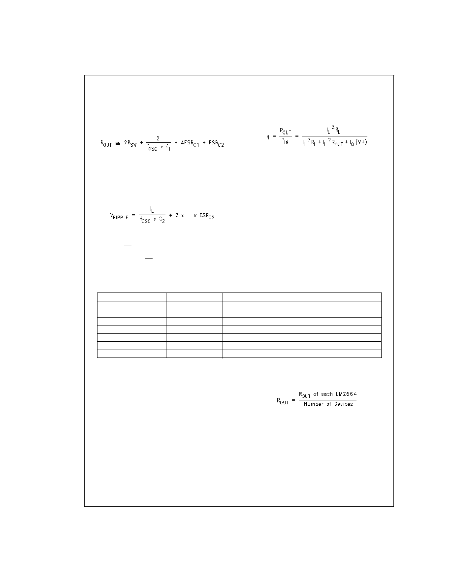
once in the output resistance. A good approximation of R
out
is:
where R
SW is the sum of the ON resistance of the internal
MOSFET switches shown in
Figure 2.
High capacitance, low ESR capacitors will reduce the output
resistance.
The peak-to-peak output voltage ripple is determined by the
oscillator frequency, the capacitance and ESR of the output
capacitor C
2:
Again, using a low ESR capacitor will result in lower ripple.
Shutdown Mode
A shutdown (SD ) pin is available to disable the device and
reduce the quiescent current to 1A. Applying a voltage less
than 20% of V+ to the SD pin will bring the device into shut-
down mode. While in normal operating mode, the pin is con-
nected to V+.
Capacitor Selection
As discussed in the
Simple Negative Voltage Converter sec-
tion, the output resistance and ripple voltage are dependent
on the capacitance and ESR values of the external capaci-
tors. The output voltage drop is the load current times the
output resistance, and the power efficiency is
Where I
Q(V+) is the quiescent power loss of the IC device,
and I
L
2R
out is the conversion loss associated with the switch
on-resistance, the two external capacitors and their ESRs.
The selection of capacitors is based on the specifications of
the dropout voltage (which equals I
out Rout), the output volt-
age ripple, and the converter efficiency. Low ESR capacitors
(Table 1) are recommended to maximize efficiency, reduce
the output voltage drop and voltage ripple.
Low ESR Capacitor Manufacturers
Manufacturer
Phone
Capacitor Type
Nichicon Corp.
(708)-843-7500
PL & PF series, through-hole aluminum electrolytic
AVX Corp.
(803)-448-9411
TPS series, surface-mount tantalum
Sprague
(207)-324-4140
593D, 594D, 595D series, surface-mount tantalum
Sanyo
(619)-661-6835
OS-CON series, through-hole aluminum electrolytic
Murata
(800)-831-9172
Ceramic chip capacitors
Taiyo Yuden
(800)-348-2496
Ceramic chip capacitors
Tokin
(408)-432-8020
Ceramic chip capacitors
Other Applications
Paralleling Devices
Any number of LM2664s can be paralleled to reduce the out-
put resistance. Each device must have its own pumping ca-
pacitor C
1, while only one output capacitor Cout is needed as
shown in Figure 3. The composite output resistance is:
LM2664
www.national.com
6
相关PDF资料 |
PDF描述 |
|---|---|
| LM2704MFX-ADJ/NOPB | 0.62 A SWITCHING REGULATOR, PDSO5 |
| LM2710MTX-ADJ/NOPB | 1.4 A SWITCHING REGULATOR, 1500 kHz SWITCHING FREQ-MAX, PDSO20 |
| LM2710MT-ADJ/NOPB | 1.4 A SWITCHING REGULATOR, 1500 kHz SWITCHING FREQ-MAX, PDSO20 |
| LM2984MDC | 1-CHANNEL POWER SUPPLY SUPPORT CKT, UUC |
| LM3207TL/NOPB | 1.2 A SWITCHING REGULATOR, 2300 kHz SWITCHING FREQ-MAX, PBGA9 |
相关代理商/技术参数 |
参数描述 |
|---|---|
| LM2665 | 制造商:未知厂家 制造商全称:未知厂家 功能描述: |
| LM2665M6 | 功能描述:电荷泵 RoHS:否 制造商:Maxim Integrated 功能:Inverting, Step Up 输出电压:- 1.5 V to - 5.5 V, 3 V to 11 V 输出电流:100 mA 电源电流:1 mA 最大工作温度:+ 70 C 封装 / 箱体:SOIC-8 Narrow 封装:Tube |
| LM2665M6/NOPB | 功能描述:电荷泵 SWITCHED CAPACITOR VLTG CONVERTER RoHS:否 制造商:Maxim Integrated 功能:Inverting, Step Up 输出电压:- 1.5 V to - 5.5 V, 3 V to 11 V 输出电流:100 mA 电源电流:1 mA 最大工作温度:+ 70 C 封装 / 箱体:SOIC-8 Narrow 封装:Tube |
| LM2665M6/NOPB | 制造商:Texas Instruments 功能描述:DC/DC Charge Pump Converter (DC-DC) IC |
| LM2665M6X | 功能描述:电荷泵 RoHS:否 制造商:Maxim Integrated 功能:Inverting, Step Up 输出电压:- 1.5 V to - 5.5 V, 3 V to 11 V 输出电流:100 mA 电源电流:1 mA 最大工作温度:+ 70 C 封装 / 箱体:SOIC-8 Narrow 封装:Tube |
发布紧急采购,3分钟左右您将得到回复。