- 您现在的位置:买卖IC网 > PDF目录44550 > LM2670T-5.0EP (NATIONAL SEMICONDUCTOR CORP) 5.4 A SWITCHING REGULATOR, 280 kHz SWITCHING FREQ-MAX, PZFM7 PDF资料下载
参数资料
| 型号: | LM2670T-5.0EP |
| 厂商: | NATIONAL SEMICONDUCTOR CORP |
| 元件分类: | 稳压器 |
| 英文描述: | 5.4 A SWITCHING REGULATOR, 280 kHz SWITCHING FREQ-MAX, PZFM7 |
| 封装: | PLASTIC, TO-220, 7 PIN |
| 文件页数: | 6/25页 |
| 文件大小: | 465K |
| 代理商: | LM2670T-5.0EP |
Application Hints (Continued)
rms current rating greater than 1.25A (1/2 I
load max). Again
using Table 2 for specific component characteristics the
following choices are suitable:
1 x 1000F/63V Sanyo MV-GX (code C14)
1 x 820F/63V Nichicon PL (code C24)
1 x 560F/50V Panasonic HFQ (code C13)
Step 6: From Table5a3A Schottky diode must be selected.
For through-hole components 20V rated diodes are sufficient
and 2 part types are suitable:
1N5820
SR302
Step 7: A 0.01F capacitor will be used for Cboost.
ADJUSTABLE OUTPUT DESIGN EXAMPLE
In this example it is desired to convert the voltage from a two
battery automotive power supply (voltage range of 20V to
28V, typical in large truck applications) to the 14.8VDC alter-
nator supply typically used to power electronic equipment
from single battery 12V vehicle systems. The load current
required is 2A maximum. It is also desired to implement the
power supply with all surface mount components.
Step 1: Operating conditions are:
Vout = 14.8V
Vin max = 28V
Iload max = 2A
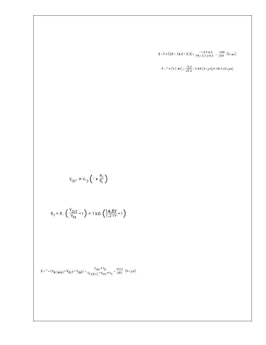
Step 2: Select an LM2670S-ADJEP. To set the output volt-
age to 14.9V two resistors need to be chosen (R1 and R2 in
Figure 2). For the adjustable device the output voltage is set
by the following relationship:
Where V
FB is the feedback voltage of typically 1.21V.
A recommended value to use for R1 is 1K. In this example
then R2 is determined to be:
R2 = 11.23K
The closest standard 1% tolerance value to use is 11.3K
This will set the nominal output voltage to 14.88V which is
within 0.5% of the target value.
Step 3: To use the nomograph for the adjustable device,
requires
a
calculation
of
the
inductor
Volt
microsecond constant (ET expressed in VS) from
the following formula:
where V
SAT is the voltage drop across the internal power
switch which is R
ds(ON) times Iload. In this example this would
be typically 0.15
x 2A or 0.3V and V
D is the voltage drop
across the forward bisased Schottky diode, typically 0.5V.
The switching frequency of 260KHz is the nominal value to
use to estimate the ON time of the switch during which
energy is stored in the inductor.
For this example E
T is found to be:
Using Figure 6, the intersection of 27V
S horizontally and
the 2A vertical line (I
load max) indicates that L38 , a 68H
inductor, should be used.
From Table 1, L38 in a surface mount component is available
from Pulse Engineering with part number PE-54038S.
Step 4: Use Table 6 to determine an output capacitor. With a
14.8V output the 12.5 to 15V row is used and with a 68H
inductor there are three surface mount output capacitor so-
lutions. Table 2 provides the actual capacitor characteristics
based on the C Code number. Any of the following choices
can be used:
1 x 33F/20V AVX TPS (code C6)
1 x 47F/20V Sprague 594 (code C8)
1 x 47F/20V Kemet T495 (code C8)
Important Note: When using the adjustable device in low
voltage applications (less than 3V output), if the nomograph,
Figure 6, selects an inductance of 22H or less, Table 6 does
not provide an output capacitor solution. With these condi-
tions the number of output capacitors required for stable
operation becomes impractical. It is recommended to use
either a 33H or 47H inductor and the output capacitors
from Table 6.
Step 5: An input capacitor for this example will require at
least a 35V WV rating with an rms current rating of 1A (1/2
Iout max). From Table 2 it can be seen that C12, a 33F/35V
capacitor from Sprague, has the required voltage/current
rating of the surface mount components.
Step 6: From Table5a3A Schottky diode must be selected.
For surface mount diodes with a margin of safety on the
voltage rating one of five diodes can be used:
SK34
30BQ040
30WQ04F
MBRS340
MBRD340
Step 7: A 0.01F capacitor will be used for Cboost.
LLP PACKAGE DEVICES
The LM2670EP may be offered in the 14 lead LLP surface
mount package to allow for a significantly decreased foot-
print with equivalent power dissipation compared to the TO-
263. For details on mounting and soldering specifications,
refer
to
Application
Note
AN-1187
at
http://
power.national.com. .
LM2670EP
Enhanced
Plastic
www.national.com
14
相关PDF资料 |
PDF描述 |
|---|---|
| LM2670S-12EP | 5.4 A SWITCHING REGULATOR, 280 kHz SWITCHING FREQ-MAX, PSSO7 |
| LM2670SD-5.0EP | 5.4 A SWITCHING REGULATOR, 280 kHz SWITCHING FREQ-MAX, PDSO14 |
| LM2670SD-3.3EP | 5.4 A SWITCHING REGULATOR, 280 kHz SWITCHING FREQ-MAX, PDSO14 |
| LM2670T-12EP | 5.4 A SWITCHING REGULATOR, 280 kHz SWITCHING FREQ-MAX, PZFM7 |
| LM2670S-5.0EP | 5.4 A SWITCHING REGULATOR, 280 kHz SWITCHING FREQ-MAX, PSSO7 |
相关代理商/技术参数 |
参数描述 |
|---|---|
| LM2670T-ADJ | 功能描述:直流/直流开关转换器 RoHS:否 制造商:STMicroelectronics 最大输入电压:4.5 V 开关频率:1.5 MHz 输出电压:4.6 V 输出电流:250 mA 输出端数量:2 最大工作温度:+ 85 C 安装风格:SMD/SMT |
| LM2670T-ADJ/NOPB | 功能描述:直流/直流开关转换器 RoHS:否 制造商:STMicroelectronics 最大输入电压:4.5 V 开关频率:1.5 MHz 输出电压:4.6 V 输出电流:250 mA 输出端数量:2 最大工作温度:+ 85 C 安装风格:SMD/SMT |
| LM2670T-ADJ/NOPB | 制造商:Texas Instruments 功能描述:DC/DC Converter IC |
| LM2671 | 制造商:未知厂家 制造商全称:未知厂家 功能描述: |
| LM2671_07 | 制造商:NSC 制造商全称:National Semiconductor 功能描述:SIMPLE SWITCHER㈢ Power Converter High Efficiency 500mA Step-Down Voltage Regulator with Features |
发布紧急采购,3分钟左右您将得到回复。