- 您现在的位置:买卖IC网 > PDF目录44550 > LM2672-3.3MWC (NATIONAL SEMICONDUCTOR CORP) 2.2 A SWITCHING REGULATOR, 275 kHz SWITCHING FREQ-MAX, UUC PDF资料下载
参数资料
| 型号: | LM2672-3.3MWC |
| 厂商: | NATIONAL SEMICONDUCTOR CORP |
| 元件分类: | 稳压器 |
| 英文描述: | 2.2 A SWITCHING REGULATOR, 275 kHz SWITCHING FREQ-MAX, UUC |
| 封装: | WAFER |
| 文件页数: | 3/30页 |
| 文件大小: | 576K |
| 代理商: | LM2672-3.3MWC |
第1页第2页当前第3页第4页第5页第6页第7页第8页第9页第10页第11页第12页第13页第14页第15页第16页第17页第18页第19页第20页第21页第22页第23页第24页第25页第26页第27页第28页第29页第30页
LM2672 Series Buck Regulator Design Procedure (Fixed Output) (Continued)
PROCEDURE (Fixed Output Voltage Version)
EXAMPLE (Fixed Output Voltage Version)
4. Input Capacitor (C
IN)
A low ESR aluminum or tantalum bypass capacitor is needed
between the input pin and ground to prevent large voltage
transients from appearing at the input. This capacitor should be
located close to the IC using short leads. In addition, the RMS
current rating of the input capacitor should be selected to be at
least 12 the DC load current. The capacitor manufacturer data
sheet must be checked to assure that this current rating is not
exceeded. The curves shown in
Figure 14 show typical RMS
current ratings for several different aluminum electrolytic
capacitor values. A parallel connection of two or more
capacitors may be required to increase the total minimum RMS
current rating to suit the application requirements.
For an aluminum electrolytic capacitor, the voltage rating should
be at least 1.25 times the maximum input voltage. Caution must
be exercised if solid tantalum capacitors are used. The tantalum
capacitor voltage rating should be twice the maximum input
voltage. The tables in
Figure 15 show the recommended
application voltage for AVX TPS and Sprague 594D tantalum
capacitors. It is also recommended that they be surge current
tested by the manufacturer. The TPS series available from AVX,
and the 593D and 594D series from Sprague are all surge
current tested. Another approach to minimize the surge current
stresses on the input capacitor is to add a small inductor in
series with the input supply line.
Use caution when using ceramic capacitors for input bypassing,
because it may cause severe ringing at the V
IN pin.
4. Input Capacitor (C
IN)
The important parameters for the input capacitor are the input
voltage rating and the RMS current rating. With a maximum
input voltage of 12V, an aluminum electrolytic capacitor with a
voltage rating greater than 15V (1.25 x V
IN) would be needed.
The next higher capacitor voltage rating is 16V.
The RMS current rating requirement for the input capacitor in a
buck regulator is approximately 12 the DC load current. In this
example, with a 1A load, a capacitor with a RMS current rating
of at least 500 mA is needed. The curves shown in
can be used to select an appropriate input capacitor. From the
curves, locate the 16V line and note which capacitor values
have RMS current ratings greater than 500 mA.
For a through hole design, a 330 F/16V electrolytic capacitor
(Panasonic HFQ series, Nichicon PL, Sanyo MV-GX series or
equivalent) would be adequate. Other types or other
manufacturers’ capacitors can be used provided the RMS ripple
current ratings are adequate. Additionally, for a complete
surface mount design, electrolytic capacitors such as the Sanyo
CV-C or CV-BS and the Nichicon WF or UR and the NIC
Components NACZ series could be considered.
For surface mount designs, solid tantalum capacitors can be
used, but caution must be exercised with regard to the capacitor
surge current rating and voltage rating. In this example,
checking Figure 15, and the Sprague 594D series datasheet, a
Sprague 594D 15 F, 25V capacitor is adequate.
5. Boost Capacitor (C
B)
This capacitor develops the necessary voltage to turn the switch
gate on fully. All applications should use a 0.01 F, 50V ceramic
capacitor.
5. Boost Capacitor (C
B)
For this application, and all applications, use a 0.01 F, 50V
ceramic capacitor.
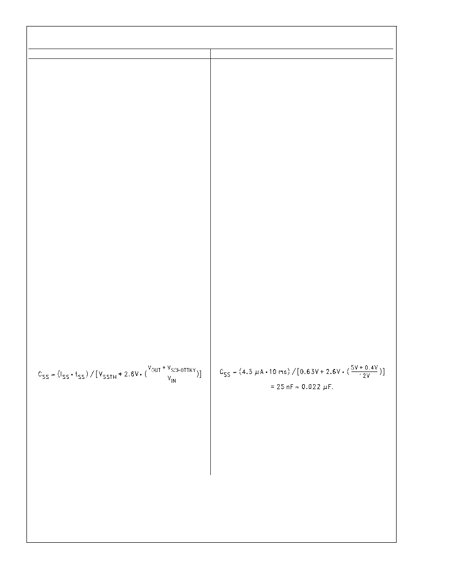
6. Soft-Start Capacitor (C
SS - optional)
This capacitor controls the rate at which the device starts up.
The formula for the soft-start capacitor C
SS is:
6. Soft-Start Capacitor (C
SS - optional)
For this application, selecting a start-up time of 10 ms and using
the formula for C
SS results in a value of:
where:
I
SS
= Soft-Start Current
:4.5 A typical.
t
SS
= Soft-Start Time
:Selected.
V
SSTH
= Soft-Start Threshold Voltage
:0.63V typical.
V
OUT
= Output Voltage
:Selected.
V
SCHOTTKY
= Schottky Diode Voltage Drop
:0.4V typical.
V
IN
= Input Voltage
:Selected.
If this feature is not desired, leave this pin open.
LM2672
www.national.com
11
相关PDF资料 |
PDF描述 |
|---|---|
| LM2672-ADJMWC | 2.2 A SWITCHING REGULATOR, 275 kHz SWITCHING FREQ-MAX, UUC |
| LM2672-12MDC | 2.2 A SWITCHING REGULATOR, 275 kHz SWITCHING FREQ-MAX, UUC |
| LM2672M-3.3X | 2.2 A SWITCHING REGULATOR, 275 kHz SWITCHING FREQ-MAX, PDSO8 |
| LM2672M-5.0X | 2.2 A SWITCHING REGULATOR, 275 kHz SWITCHING FREQ-MAX, PDSO8 |
| LM2672LD-5.0/NOPB | 2.2 A SWITCHING REGULATOR, 275 kHz SWITCHING FREQ-MAX, PDSO16 |
相关代理商/技术参数 |
参数描述 |
|---|---|
| LM2672EP | 制造商:NSC 制造商全称:National Semiconductor 功能描述:Enhanced Plastic SIMPLE SWITCHER Power Converter High Efficiency 1A Step-Down Voltage Regulator with Features |
| LM2672LD-12 | 制造商:NSC 制造商全称:National Semiconductor 功能描述:SIMPLE SWITCHER㈢ Power Converter High Efficiency 1A Step-Down Voltage Regulator with Features |
| LM2672LD-12/NOPB | 功能描述:IC REG BUCK 12V 1A 16LLP RoHS:是 类别:集成电路 (IC) >> PMIC - 稳压器 - DC DC 开关稳压器 系列:SIMPLE SWITCHER® 产品培训模块:Lead (SnPb) Finish for COTS Obsolescence Mitigation Program 标准包装:1 系列:- 类型:降压(降压) 输出类型:固定 输出数:1 输出电压:3.3V 输入电压:4.5 V ~ 24 V PWM 型:- 频率 - 开关:- 电流 - 输出:125mA 同步整流器:无 工作温度:-40°C ~ 85°C 安装类型:表面贴装 封装/外壳:SOT-23-6 包装:Digi-Reel® 供应商设备封装:SOT-6 其它名称:MAX1836EUT33#TG16DKR |
| LM2672LD-3.3 | 制造商:未知厂家 制造商全称:未知厂家 功能描述: |
| LM2672LD-3.3/NOPB | 功能描述:IC REG BUCK 3.3V 1A 16-LLP RoHS:是 类别:集成电路 (IC) >> PMIC - 稳压器 - DC DC 开关稳压器 系列:SIMPLE SWITCHER® 产品培训模块:Lead (SnPb) Finish for COTS Obsolescence Mitigation Program 标准包装:1 系列:- 类型:降压(降压) 输出类型:固定 输出数:1 输出电压:3.3V 输入电压:4.5 V ~ 24 V PWM 型:- 频率 - 开关:- 电流 - 输出:125mA 同步整流器:无 工作温度:-40°C ~ 85°C 安装类型:表面贴装 封装/外壳:SOT-23-6 包装:Digi-Reel® 供应商设备封装:SOT-6 其它名称:MAX1836EUT33#TG16DKR |
发布紧急采购,3分钟左右您将得到回复。