- 您现在的位置:买卖IC网 > PDF目录79789 > LM3661TLX-1.25 (NATIONAL SEMICONDUCTOR CORP) 0.454 A SWITCHING REGULATOR, 675 kHz SWITCHING FREQ-MAX, PBGA10 PDF资料下载
参数资料
| 型号: | LM3661TLX-1.25 |
| 厂商: | NATIONAL SEMICONDUCTOR CORP |
| 元件分类: | 稳压器 |
| 英文描述: | 0.454 A SWITCHING REGULATOR, 675 kHz SWITCHING FREQ-MAX, PBGA10 |
| 封装: | MICRO SMD-10 |
| 文件页数: | 6/17页 |
| 文件大小: | 845K |
| 代理商: | LM3661TLX-1.25 |
Application Information (Continued)
INDUCTOR SELECTION
There are a few things that one must consider when select-
ing an inductor for an application. They are the inductor DC
current rating, inductor ripple current, DC-resistance of the
inductor and value of the inductor. The DC current rating of
the inductor denotes the maximum current before the induc-
tor core enters saturation. Before selecting the DC current
rating of the inductor, an inductor ripple current must be
determined using Equation (1). The DC current of the induc-
tor should be the maximum output current of the circuit plus
half of the peak to peak current ripple of the inductor using
(1)
(2)
A good estimate for the inductor ripple current would be
using a operation condition or assume the inductor ripple
current to be about 30% of the maximum output current of
the device. Consider the following example for LM3661
(when I
SEL = L); a 10 H, 450 mA load current with 1.4V
output operates at 4.5V input and 600kHz in an application,
solving for
I
L using Equation (2) yields
I
L = 160 mA.
Therefore the maximum peak current (Equation (1)) in the
application will be 530 mA (I
O + 1/2
I
L). Thus, an inductor
with DC current rating of 600 mA or higher should suffice for
the application when I
SEL = L. For a more conservative
approach, it is best to select an inductor with a current rating
of the maximum switch peak current of the device. Note that
If smaller inductor is used in the application, the larger the
inductor ripple current (Equation (1)). Care must be taken to
select the inductor such that the peak current rating of the
inductor accounts for minimum inductance and maximum
current for the operating condition. Equation (3) can be used
to calculate the inductor value if the application conditions
are known:
(3)
Where f is the operating frequency,
I
L is the inductor current
ripple and Vo is the desired output.
Finally, the DC resistance (DCR) of the inductor also affect
the overall efficiency of the solution. Lower DCR is recom-
mended for better efficiency in handheld and battery oper-
ated applications. Consult inductor manufacture for this
specification. Table 2 lists suggested inductors and suppli-
ers.
Table2. Suggested Inductor and Suppliers
Part Number
Vendor
Web
D01608C-103
Coilcraft
www.coilcraft.com
P1174.103T
Pulse
www.pulseeng.com
P0770.103T
Ell6GM100M
Panasonic
www.panasonic.com
INPUT AND OUTPUT CAPACITOR
The LM3661 is designed for ceramic capacitor for its input
and output filters. Ceramic capacitors such as X5R and X7R
are recommended to use for input and output filters. These
provide an optimal balance between small size, cost, reliabil-
ity and performance. Do not use Y5V ceramic capacitors as
they have poor dielectrics performance over temperature
and voltage characteristics for a given value. Table 2 lists
suggested capacitors and suppliers.
A 10 F input and 22 F output ceramic capacitors are
suggested in figure 2 (Typical application circuit) for optimal
performance.
The input filter capacitor supplies current to the PFET switch
of the LM3661 in the first part of each cycle and reduces
voltage ripple imposed on the input power source. The out-
put filter capacitor smooths out current flow from the inductor
and reduce output voltage ripple. These capacitors must be
selected with sufficient capacitance and sufficiently low ESR
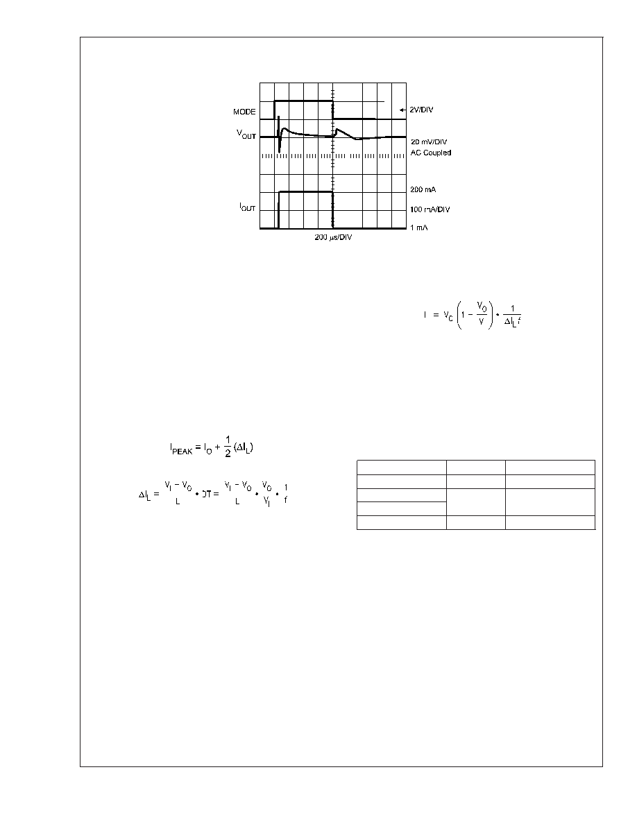
20098833
FIGURE 3.
LM3661
www.national.com
14
相关PDF资料 |
PDF描述 |
|---|---|
| LM2575T-ADJLB03 | 3.2 A SWITCHING REGULATOR, 63 kHz SWITCHING FREQ-MAX, PZFM5 |
| LT3748EMS#TRPBF | SWITCHING CONTROLLER, PDSO12 |
| LM1001-7RD9AFU | 1-OUTPUT AC-DC REG PWR SUPPLY MODULE |
| LM1001-9PD9AFU | 1-OUTPUT AC-DC REG PWR SUPPLY MODULE |
| LM1301-7RD8AFU | 1-OUTPUT AC-DC REG PWR SUPPLY MODULE |
相关代理商/技术参数 |
参数描述 |
|---|---|
| LM3668 | 制造商:NSC 制造商全称:National Semiconductor 功能描述:1A, High Efficiency Dual Mode Single Inductor Buck-Boost DC/DC Converter |
| LM3668_08 | 制造商:NSC 制造商全称:National Semiconductor 功能描述:1A, High Efficiency Dual Mode Single Inductor Buck-Boost DC/DC Converter |
| LM3668_0809 | 制造商:NSC 制造商全称:National Semiconductor 功能描述:1A, High Efficiency Dual Mode Single Inductor Buck-Boost DC/DC Converter |
| LM3668QDNTRQ1 | 功能描述:Buck-Boost Switching Regulator IC Positive Programmable 4.5V, 5V 1 Output 1A 12-WFDFN Exposed Pad 制造商:texas instruments 系列:汽车级,AEC-Q100 包装:剪切带(CT) 零件状态:有效 功能:升压/降压 输出配置:正 拓扑:降压-升压 输出类型:可编程 输出数:1 电压 - 输入(最小值):2.7V 电压 - 输入(最大值):5.5V 电压 - 输出(最小值/固定):4.5V,5V 电压 - 输出(最大值):- 电流 - 输出:1A 频率 - 开关:1.9MHz ~ 2.5MHz 同步整流器:是 工作温度:-40°C ~ 125°C (TJ) 安装类型:表面贴装 封装/外壳:12-WFDFN 裸露焊盘 供应商器件封装:12-WSON(4x4) 标准包装:1 |
| LM3668SD-2833 | 制造商:Texas Instruments 功能描述:Conv DC-DC Single Non-Inv/Inv/Step Up/Step Down 2.5V to 5.5V 12-Pin LLP EP T/R 制造商:Texas Instruments 功能描述:2.05 A DUAL SWITCHING CONTROLLER, 2500 kHz SWITCHING FREQ-MAX, PDSO12 |
发布紧急采购,3分钟左右您将得到回复。