- 您现在的位置:买卖IC网 > PDF目录10808 > LM393DT (Rohm Semiconductor)IC COMPARATOR DUAL 0.4MA 8-SOIC PDF资料下载
参数资料
| 型号: | LM393DT |
| 厂商: | Rohm Semiconductor |
| 文件页数: | 3/6页 |
| 文件大小: | 0K |
| 描述: | IC COMPARATOR DUAL 0.4MA 8-SOIC |
| 标准包装: | 1 |
| 系列: | 签名 |
| 类型: | 通用 |
| 元件数: | 2 |
| 输出类型: | CMOS,MOS,开路集电极,TTL |
| 电压 - 电源,单路/双路(±): | 2 V ~ 36 V,±1 V ~ 18 V |
| 电压 - 输入偏移(最小值): | 7mV @ 5V |
| 电流 - 输入偏压(最小值): | 0.25µA @ 5V |
| 电流 - 输出(标准): | 16mA @ 5V |
| 电流 - 静态(最大值): | 2.5mA |
| 工作温度: | 0°C ~ 70°C |
| 封装/外壳: | 8-SOIC(0.154",3.90mm 宽) |
| 安装类型: | 表面贴装 |
| 包装: | 标准包装 |
| 产品目录页面: | 1377 (CN2011-ZH PDF) |
| 其它名称: | LM393DTDKR |
3
Precision Edge
SY89223L
Micrel, Inc.
M9999-051805
hbwhelp@micrel.com or (408) 955-1690
Absolute Maximum Ratings(Note 1)
Power Supply Voltage (V
CC) ......................... –0.5V to 4.0V
PECL Input Voltage (V
IN) ........................ +0V to VCC +0.5V
Voltage Applied to Output at HIGH State
(V
OUT) ....................................................... –0.5V to VCC
Current Applied to Output at LOW State
(I
OUT) ........................................ Twice the Rated IOL mA
Lead Temperature (soldering, 20 sec.) ..................... 260
°C
Storage Temperature (T
S) ....................... –65°C to +150°C
Operating Ratings(Note 2)
Power Supply Voltage (V
CC) ....................... +3.0V to +3.6V
Ambient Temperature (T
A) ......................... –40°C to +85°C
Package Thermal Resistance,(Note 3)
MLF
(θ
JA)
Still-Air ............................................................. 93
°C/W
500lfpm ............................................................ 87
°C/W
MLF
(ψ
JB), ....................................................... 56°C/W
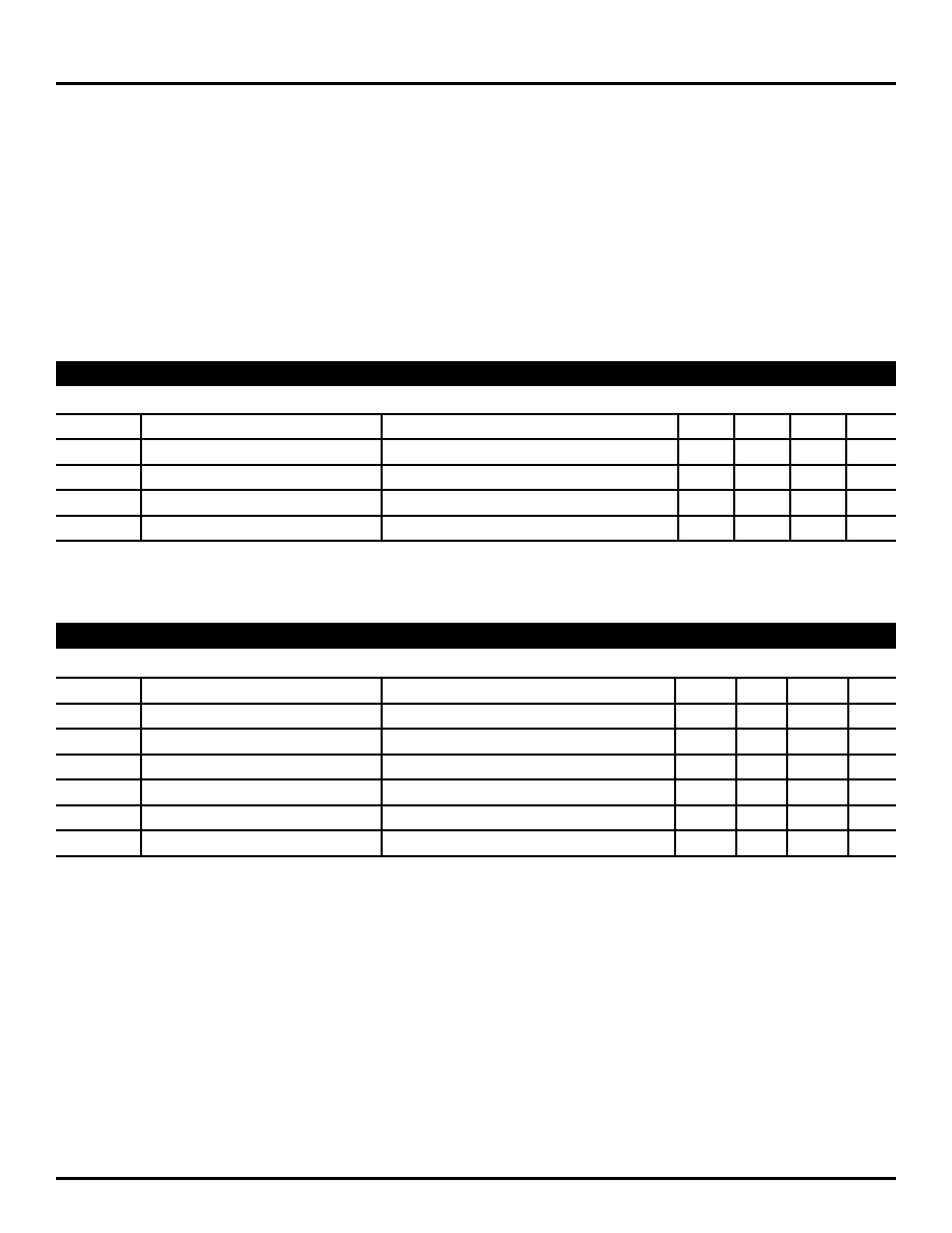
V
CC = 3.3V ±10%; GND = 0V, TA = –40°C to +85°C; unless otherwise noted.
Symbol
Parameter
Condition
Min
Typ
Max
Units
V
OH
Output HIGH Voltage
I
OH = –3.0mA
2.0
V
OL
Output LOW Voltage
I
OL = 24mA
0.5
V
I
CC
Power Supply Current
30
mA
I
OS
Output Short Circuit Current
V
OUT = 0V
–80
–240
mA
LVTTL DC ELECTRICAL CHARACTERISTICS
V
CC = 3.3V ±10%; GND = 0V, TA = –40°C to +85°C; unless otherwise noted.
Symbol
Parameter
Condition
Min
Typ
Max
Units
V
IH
Input HIGH Voltage
V
CC–1.165
—
V
CC–0.880
V
IL
Input LOW Voltage
V
CC–1.810
—
V
CC–1.475
V
IHCMR
Input HIGH Common Mode Range
Note 4
1.2
—
V
CC
V
PP
Minimum Input Swing
200
—
mV
I
IH
Input HIGH Current
—
150
A
I
IL
Input LOW Current
0.5
—
A
Note 1.
Permanent device damage may occur if ABSOLUTE MAXIMUM RATINGS are exceeded. This is a stress rating only and functional operation is
not implied at conditions other than those detailed in the operational sections of this data sheet. Exposure to ABSOLUTE MAXIMUM RATlNG
conditions for extended periods may affect device reliability.
Note 2.
The data sheet limits are not guaranteed if the device is operated beyond the operating ratings.
Note 3.
Package thermal resistance assumes exposed pad is soldered (or equivalent) to the device's most negative potential on the PCB.
Note 4.
V
IHCMR(min) varies 1:1 with VEE, Max varies 1:1 with VCC.
LVPECL DC ELECTRICAL CHARACTERISTICS
相关PDF资料 |
PDF描述 |
|---|---|
| VE-JWN-MY-S | CONVERTER MOD DC/DC 18.5V 50W |
| VI-B4B-IV-S | CONVERTER MOD DC/DC 95V 150W |
| ADM3311EARSZ-REEL7 | IC TXRX RS-232 3:5 2.7V 28SSOP |
| LM2903DT | IC COMPARATOR DUAL 0.4MA 8-SOIC |
| ADM3075EARZ | IC TXRX RS-485 3.3V HD 8-SOIC |
相关代理商/技术参数 |
参数描述 |
|---|---|
| LM393D-T | 制造商:未知厂家 制造商全称:未知厂家 功能描述:Analog Comparator |
| LM393DT_11 | 制造商:ROHM 制造商全称:Rohm 功能描述:SIGNATURE SERIES Comparators |
| LM393DT-CUT TAPE | 制造商:ST 功能描述:LM393 Series Dual 36 V 250 nA SMT Low Power Voltage Comparator - SOIC-8 |
| LM393EDT | 制造商:STMicroelectronics 功能描述:SO 08 .15 JEDEC - Tape and Reel |
| LM393F | 制造商:KEC 制造商全称:KEC(Korea Electronics) 功能描述:BIPOLAR LINEAR INTEGRATED CIRCUIT DUAL COMPARATOR |
发布紧急采购,3分钟左右您将得到回复。