- 您现在的位置:买卖IC网 > PDF目录30751 > LM4752MDC (NATIONAL SEMICONDUCTOR CORP) 7 W, 2 CHANNEL, AUDIO AMPLIFIER, UUC PDF资料下载
参数资料
| 型号: | LM4752MDC |
| 厂商: | NATIONAL SEMICONDUCTOR CORP |
| 元件分类: | 音频/视频放大 |
| 英文描述: | 7 W, 2 CHANNEL, AUDIO AMPLIFIER, UUC |
| 封装: | DIE |
| 文件页数: | 4/21页 |
| 文件大小: | 732K |
| 代理商: | LM4752MDC |
Application Information (Continued)
put signal. An external circuit may be used to sense for the
desired threshold, and pull the bias line (pin5) to ground to
disable the input preamp.
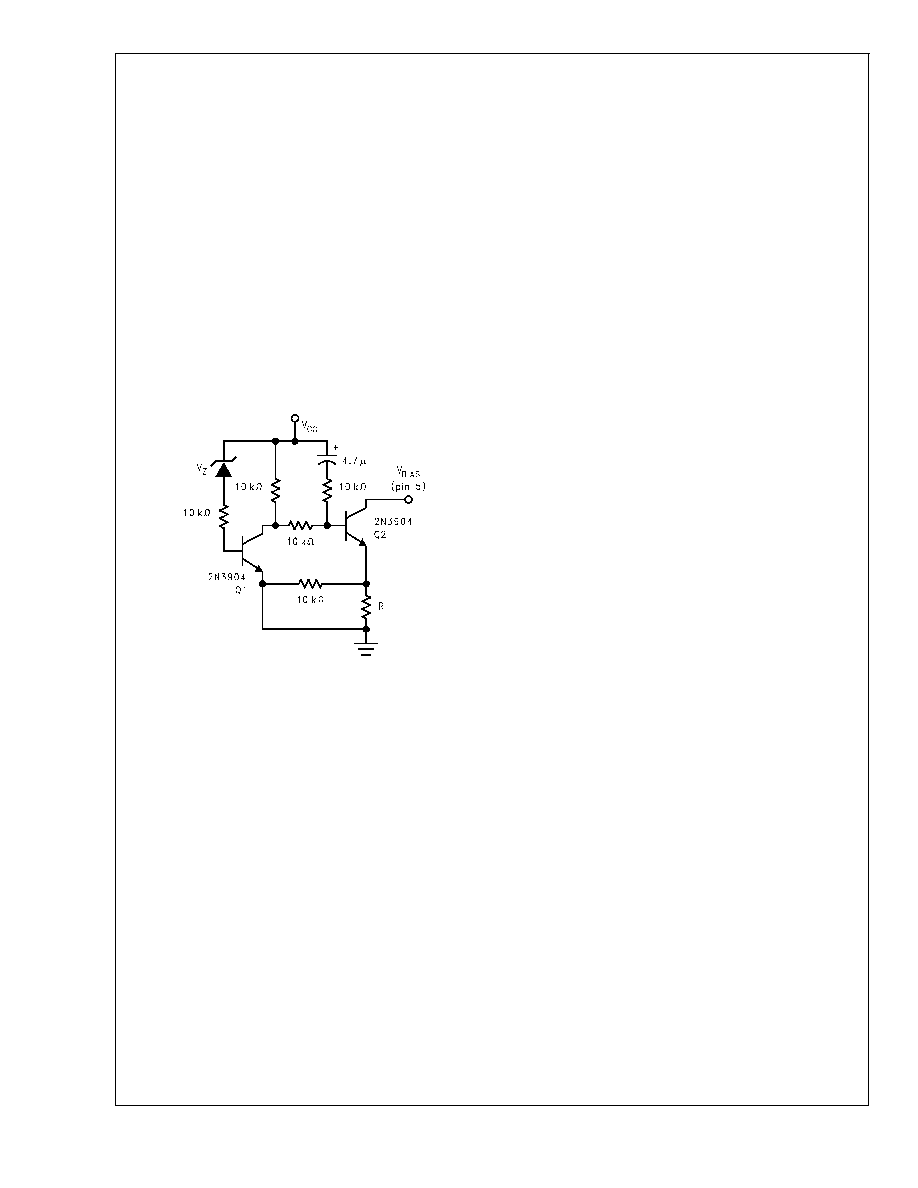
Figure 7 shows an example of
such a circuit. When the voltage across the zener diode
drops below its threshold, current flow into the base of Q1 is
interrupted. Q2 then turns on, discharging the bias capacitor.
This discharge rate is governed by several factors, including
the bias capacitor value, the bias voltage, and the resistor at
the emitter of Q2. An equation for approximating the value of
the emitter discharge resistor, R, is given below:
R = (0.7V) / (C
B (V S / 2) / 0.1s)
Note that this is only a linearized approximation based on a
discharge time of 0.1s. The circuit should be evaluated and
adjusted for each application.
As mentioned earlier in the Application Circuit with Mute
section, when using an external circuit to pull down the bias
line, the rate of discharge will have an effect on the turn-off
induced distortions. Please refer to the Application Circuit
with Mute section for more information.
THERMAL CONSIDERATIONS
Heat Sinking
Proper heatsinking is necessary to ensure that the amplifier
will function correctly under all operating conditions. A heat-
sink that is too small will cause the die to heat excessively
and will result in a degraded output signal as the internal
thermal protection circuitry begins to operate.
The choice of a heatsink for a given application is dictated by
several factors: the maximum power the IC needs to dissi-
pate, the worst-case ambient temperature of the circuit, the
junction-to-case thermal resistance, and the maximum junc-
tion temperature of the IC. The heat flow approximation
equation used in determining the correct heatsink maximum
thermal resistance is given below:
T
J–TA =P DMAX (θJC + θCS + θ SA)
where:
P
DMAX = maximum power dissipation of the IC
T
J(C) = junction temperature of the IC
T
A(C) = ambient temperature
θ
JC(C/W) = junction-to-case thermal resistance of the IC
θ
CS(C/W) = case-to-heatsink thermal resistance (typically
0.2 to 0.5 C/W)
θ
SA(C/W) = thermal resistance of heatsink
When determining the proper heatsink, the above equation
should be re-written as:
θ
SA ≤ [(TJ TA)/PDMAX] θ JC θCS
TO-263 HEATSINKING
Surface mount applications will be limited by the thermal dis-
sipation properties of printed circuit board area. The TO-263
package is not recommended for surface mount applications
with V
S > 16V due to limited printed circuit board area.
There are TO-263 package enhancements, such as clip-on
heatsinks and heatsinks with adhesives, that can be used to
improve performance.
Standard FR-4 single-sided copper clad will have an ap-
proximate Thermal resistance (
θ
SA) ranging from:
1.5 x 1.5 in. sq.
20–27C/W
(T
A=28C, Sine wave
testing, 1 oz. Copper)
2 x 2 in. sq.
16–23C/W
The above values for
θ
SA vary widely due to dimensional
proportions (i.e. variations in width and length will vary
θ
SA).
For audio applications, where peak power levels are short in
duration, this part will perform satisfactory with less
heatsinking/copper clad area. As with any high power design
proper bench testing should be undertaken to assure the de-
sign can dissipate the required power. Proper bench testing
requires attention to worst case ambient temperature and air
flow. At high power dissipation levels the part will show a ten-
dency to increase saturation voltages, thus limiting the un-
distorted power levels.
Determining Maximum Power Dissipation
For a single-ended class AB power amplifier, the theoretical
maximum power dissipation point is a function of the supply
voltage, V
S, and the load resistance, RL and is given by the
following equation:
(single channel)
P
DMAX (W)=[VS
2 /(2
π2 R
L)]
The above equation is for a single channel class-AB power
amplifier. For dual amplifiers such as the LM4752, the equa-
tion for calculating the total maximum power dissipated is:
(dual channel)
P
DMAX (W)=2 [V S
2 /(2
π2 R
L)]
or
V
S
2 /(
π 2 R
L)
(Bridged Outputs)
P
DMAX (W) = 4[VS
2 /(2
π2 R
L)]
Heatsink Design Example:
Determine the system parameters:
V
S = 24V
Operating Supply Voltage
R
L =4
Minimum load impedance
T
A = 55C
Worst case ambient temperature
Device parameters from the datasheet:
T
J = 150C
Maximum junction temperature
θ
JC = 2C/W
Junction-to-case thermal resistance
Calculations:
2
P
DMAX =2 [V S
2 /(2
π2 R
L) ] = (24V)
2 /(2
π2
4
) = 14.6W
θ
SA ≤ [(TJ TA)/PDMAX] θ JC θCS = [ (150C 55C)
/ 14.6W ] 2C/W 0.2C/W = 4.3C/W
Conclusion: Choose a heatsink with
θ
SA ≤ 4.3C/W.
DS100039-32
FIGURE 7. External Undervoltage Pull-Down
LM4752
www.national.com
12
相关PDF资料 |
PDF描述 |
|---|---|
| LM4752MWC | 7 W, 2 CHANNEL, AUDIO AMPLIFIER, UUC |
| LM4752T/NOPB | 7 W, 2 CHANNEL, AUDIO AMPLIFIER, PZFM7 |
| LM4753T | 11.8 W, 2 CHANNEL, AUDIO AMPLIFIER, PZFM15 |
| LM4755MWC | 11 W, 2 CHANNEL, AUDIO AMPLIFIER, UUC |
| LM4755MDC | 11 W, 2 CHANNEL, AUDIO AMPLIFIER, UUC |
相关代理商/技术参数 |
参数描述 |
|---|---|
| LM4752T | 制造商:National Semiconductor Corporation 功能描述: 制造商:Texas Instruments 功能描述: |
| LM4752T/NOPB | 功能描述:IC AMP AUDIO PWR 11W AB TO220-7 RoHS:是 类别:集成电路 (IC) >> 线性 - 音頻放大器 系列:- 产品培训模块:Lead (SnPb) Finish for COTS Obsolescence Mitigation Program 标准包装:2,500 系列:DirectDrive® 类型:H 类 输出类型:耳机,2-通道(立体声) 在某负载时最大输出功率 x 通道数量:35mW x 2 @ 16 欧姆 电源电压:1.62 V ~ 1.98 V 特点:I²C,麦克风,静音,短路保护,音量控制 安装类型:表面贴装 供应商设备封装:25-WLP(2.09x2.09) 封装/外壳:25-WFBGA,WLCSP 包装:带卷 (TR) |
| LM4752T/NOPB | 制造商:Texas Instruments 功能描述:Audio Power Amplifier IC |
| LM4752TS | 功能描述:音频放大器 RoHS:否 制造商:STMicroelectronics 产品:General Purpose Audio Amplifiers 输出类型:Digital 输出功率: THD + 噪声: 工作电源电压:3.3 V 电源电流: 最大功率耗散: 最大工作温度: 安装风格:SMD/SMT 封装 / 箱体:TQFP-64 封装:Reel |
| LM4752TS/NOPB | 功能描述:音频放大器 STEREO 11W AUDIO PWR AMP RoHS:否 制造商:STMicroelectronics 产品:General Purpose Audio Amplifiers 输出类型:Digital 输出功率: THD + 噪声: 工作电源电压:3.3 V 电源电流: 最大功率耗散: 最大工作温度: 安装风格:SMD/SMT 封装 / 箱体:TQFP-64 封装:Reel |
发布紧急采购,3分钟左右您将得到回复。