- 您现在的位置:买卖IC网 > PDF目录30751 > LM4755MDC (NATIONAL SEMICONDUCTOR CORP) 11 W, 2 CHANNEL, AUDIO AMPLIFIER, UUC PDF资料下载
参数资料
| 型号: | LM4755MDC |
| 厂商: | NATIONAL SEMICONDUCTOR CORP |
| 元件分类: | 音频/视频放大 |
| 英文描述: | 11 W, 2 CHANNEL, AUDIO AMPLIFIER, UUC |
| 封装: | DIE |
| 文件页数: | 12/19页 |
| 文件大小: | 756K |
| 代理商: | LM4755MDC |
Absolute Maximum Ratings (Note 2)
If Military/Aerospace specified devices are required,
please contact the National Semiconductor Sales Office/
Distributors for availability and specifications.
Supply Voltage
40V
Input Voltage
±0.7V
Output Current
Internally Limited
Power Dissipation (Note 3)
62.5W
ESD Susceptability (Note 4)
2 kV
Junction Temperature
150C
Soldering Information
T Package (10 seconds)
250C
Storage Temperature
40C to 150C
Operating Ratings
Temperature Range
T
MIN ≤ TA ≤ TMAX
40C
≤ T
A ≤ +85C
Supply Voltage
9V to 32V
θ
JC
2C/W
θ
JA
76C/W
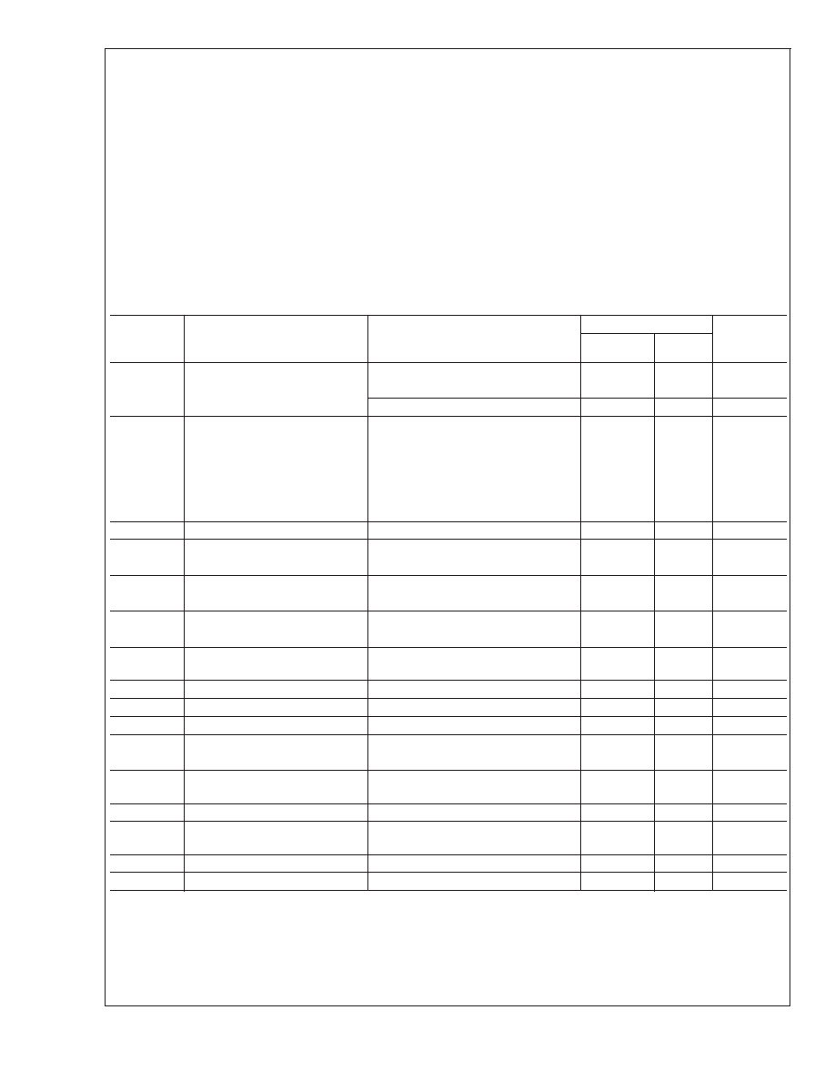
Electrical Characteristics
The following specifications apply to each channel with V
CC = 24V, TA = 25C unless otherwise specified.
Symbol
Parameter
Conditions
LM4755
Units
(Limits)
Typical
(Note 5)
Limit
I
TOTAL
Total Quiescent Power
Supply Current
Mute Off
10
15
mA(max)
7
mA(min)
Mute On
7
mA
P
O
Output Power (Continuous
Average per Channel)
f = 1 kHz, THD+N = 10%, R
L =8
7W
f = 1 kHz, THD+N = 10%, R
L =4
11
10
W(min)
V
S = 20V, RL =8
4W
V
S = 20V, RL =4
7W
f = 1 kHz, THD+N = 10%, R
L =4
V
S = 12V, TO-263 Pkg.
2.5
W
THD
Total Harmonic Distortion
f = 1 kHz, P
O = 1 W/ch, RL =8
0.08
%
V
OSW
Output Swing
P
O = 10W, RL =8
15
V
P
O = 10W, RL =4
14
V
X
TALK
Channel Separation
See Apps. Circuit
55
dB
f = 1 kHz, V
O = 4 Vrms
PSRR
Power Supply Rejection Ratio
See Apps. Circuit
50
dB
f = 120 Hz, V
O = 1 mVrms
V
ODV
Differential DC Output Offset
Voltage
V
IN = 0V
0.09
0.4
V(max)
SR
Slew Rate
2
V/s
R
IN
Input Impedance
83
k
PBW
Power Bandwidth
3 dB BW at P
O = 2.5W, RL =8
65
kHz
A
VCL
Closed Loop Gain
(Internally Set)
R
L =8
34
33
dB(min)
35
dB(max)
e
IN
Noise
IHF-A Weighting Filter, R
L =8
Output Referred
0.2
mVrms
I
O
Output Short Circuit Limit
V
IN = 0.5V, RL =2
2
A(min)
Mute Pin
V
IL
Mute Low Input Voltage
Not in Mute Mode
0.8
V(max)
V
IH
Mute High Input Voltage
In Mute Mode
2.0
2.5
V(min)
A
M
Mute Attenuation
V
MUTE = 5.0V
80
dB
Note 1: All voltages are measured with respect to the GND pin (5), unless otherwse specified.
Note 2: Absolute Maximum Ratings indicate limits beyond which damage to the device may occur. Operating Ratings indicate conditions for which the device is
functional, but do not guarantee specific performance limits. Electrical Characteristics state DC and AC electrical specifications under particular test conditions which
guarantee specific performance limits. This assumes that the device is within the Operating Ratings. Specifications are not guaranteed for parameters where no limit
is given, however, the typical value is a good indication of device performance.
Note 3: For operating at case temperatures above 25C, the device must be derated based on a 150C maximum junction temperature and a thermal resistance
of
θJC = 2C/W (junction to case). Refer to the section Determining the Maximum Power Dissipation in the Application Information section for more information.
Note 4: Human body model, 100 pF discharged through a 1.5 k
resistor.
LM4755
www.national.com
2
相关PDF资料 |
PDF描述 |
|---|---|
| LM4766MDC | 40 W, 2 CHANNEL, AUDIO AMPLIFIER, UUC |
| LM4766MWC | 40 W, 2 CHANNEL, AUDIO AMPLIFIER, UUC |
| LM4801MH/NOPB | 1.5 W, 2 CHANNEL, AUDIO AMPLIFIER, PDSO28 |
| LM4808MDC | 0.15 W, 2 CHANNEL, AUDIO AMPLIFIER, UUC |
| LM4808MWC | 0.15 W, 2 CHANNEL, AUDIO AMPLIFIER, UUC |
相关代理商/技术参数 |
参数描述 |
|---|---|
| LM4755T | 制造商:NSC 制造商全称:National Semiconductor 功能描述:Stereo 11W Audio Power Amplifier with Mute |
| LM4755T/NOPB | 功能描述:IC AMP AUDIO PWR 11W AB TO220-9 RoHS:是 类别:集成电路 (IC) >> 线性 - 音頻放大器 系列:- 产品培训模块:Lead (SnPb) Finish for COTS Obsolescence Mitigation Program 标准包装:2,500 系列:DirectDrive® 类型:H 类 输出类型:耳机,2-通道(立体声) 在某负载时最大输出功率 x 通道数量:35mW x 2 @ 16 欧姆 电源电压:1.62 V ~ 1.98 V 特点:I²C,麦克风,静音,短路保护,音量控制 安装类型:表面贴装 供应商设备封装:25-WLP(2.09x2.09) 封装/外壳:25-WFBGA,WLCSP 包装:带卷 (TR) |
| LM4755T/NOPB | 制造商:Texas Instruments 功能描述:Audio Power Amplifier IC |
| LM4755TS | 功能描述:音频放大器 RoHS:否 制造商:STMicroelectronics 产品:General Purpose Audio Amplifiers 输出类型:Digital 输出功率: THD + 噪声: 工作电源电压:3.3 V 电源电流: 最大功率耗散: 最大工作温度: 安装风格:SMD/SMT 封装 / 箱体:TQFP-64 封装:Reel |
| LM4755TS/NOPB | 功能描述:音频放大器 RoHS:否 制造商:STMicroelectronics 产品:General Purpose Audio Amplifiers 输出类型:Digital 输出功率: THD + 噪声: 工作电源电压:3.3 V 电源电流: 最大功率耗散: 最大工作温度: 安装风格:SMD/SMT 封装 / 箱体:TQFP-64 封装:Reel |
发布紧急采购,3分钟左右您将得到回复。