- 您现在的位置:买卖IC网 > PDF目录30753 > LM4856ITL/NOPB (NATIONAL SEMICONDUCTOR CORP) 1.1 W, 3 CHANNEL, AUDIO AMPLIFIER, PBGA18 PDF资料下载
参数资料
| 型号: | LM4856ITL/NOPB |
| 厂商: | NATIONAL SEMICONDUCTOR CORP |
| 元件分类: | 音频/视频放大 |
| 英文描述: | 1.1 W, 3 CHANNEL, AUDIO AMPLIFIER, PBGA18 |
| 封装: | MICRO SMD-18 |
| 文件页数: | 20/23页 |
| 文件大小: | 1321K |
| 代理商: | LM4856ITL/NOPB |
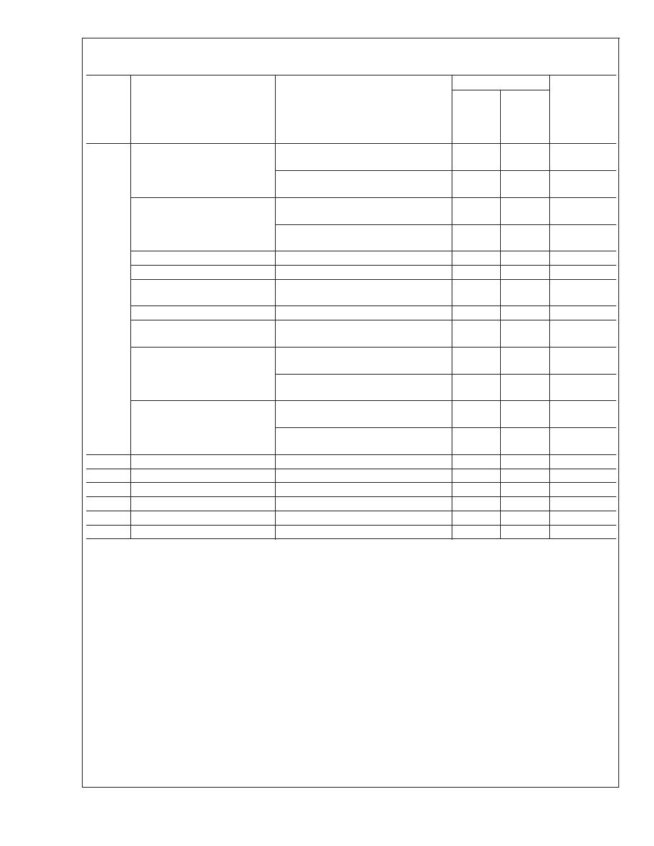
Electrical Characteristics (Notes 2, 8) (Continued)
The following specifications apply for V
DD= 3.0V, TA= 25C unless otherwise specified.
Symbol
Parameter
Conditions
LM4856
Units
(Limits)
Typical
Limits
(Notes 6,
Digital Volume Range
(R
IN and LIN)
Input referred minimum gain
-34.5
-35.1
-33.9
dB (min)
dB (max)
Input referred maximum gain
12.0
11.4
12.6
dB (min)
dB (max)
Digital Volume Range
(Phone_In_HS)
Input referred minimum gain
-40.5
-41.1
-39.9
dB (min)
dB (max)
Input referred maximum gain
6.0
5.4
6.6
dB (min)
dB (max)
Digital Volume Stepsize
1.5
dB
Digital Volume Stepsize Error
±0.1
±0.6
dB ( max)
Phone_In_IHF Volume
BTL gain from Phone_In _IHF to
SPKR
OUT
12
11.4
12.6
dB (min)
dB (max)
Phone _In_IHF Mute Attenuation
Output Mode 2, 4, 6
100
dB
Phone_In_IHF Input Impedance
20
15
25
k
(min)
k
(max)
Phone_In_HS Input Impedance
Maximum gain setting
33.5
25
42
k
(min)
k
(max)
Mininum gain setting
100
75
125
k
(min)
k
(max)
R
IN and LIN Input Impedance
Maximum gain setting
20
15
25
k
(min)
k
(max)
Mininum gain setting
100
75
125
k
(min)
k
(max)
T
SD
Thermal Shutdown Temperature
170
150
C (min)
t
1
SCL (Clock) Period
2.5
s (min)
t
2
SDA to SCL Set-up Time
100
ns (min)
t
3
Data Out Stable Time
0
ns (min)
t
4
Start Condition Time
100
ns (min)
t
5
Stop Condition Time
100
ns (min)
Note 2: Absolute Maximum Rating indicate limits beyond which damage to the device may occur.
Note 3: Operating Ratings indicate conditions for which the device is functional, but do not guarantee specific performance limits. For guaranteed specifications and
test conditions, see the Electrical Characteristics. The guaranteed specifications apply only for the test conditions listed. Some performance characteristics may
degrade when the device is not operated under the listed test conditions.
Note 4: Human body model, 100pF discharged through a 1.5k
resistor.
Note 5: Typical specifications are specified at +25C and represent the most likely parametric norm.
Note 6: Tested limits are guaranteed to National’s AOQL (Average Outgoing Quality Level).
Note 7: Machine Model ESD test is covered by specification EIAJ IC-121-1981. A 200pF cap is charged to the specified voltage, then discharged directly into the
IC with no external series resistor (resistance of discharge path must be under 50
).
Note 8: All voltages are measured with respect to the ground pin, unless otherwise specified.
Note 9: The given
θJA and θJC are for an LM4856 mounted on a demonstration board with a 4in2 area of 1oz printed circuit board copper ground plane.
Note 10: Please refer to the Output Noise vs Output Mode table in the Typical Performance Characteristics section for more details.
Note 11: Datasheet min/max specification limits are guaranteed by design, test, or statistical analysis.
LM4856
www.national.com
6
相关PDF资料 |
PDF描述 |
|---|---|
| LM4857GR/NOPB | SPECIALTY CONSUMER CIRCUIT, PBGA49 |
| LM4858MM/NOPB | 1.5 W, 2 CHANNEL, AUDIO AMPLIFIER, PDSO10 |
| LM4858LD/NOPB | 1.7 W, 2 CHANNEL, AUDIO AMPLIFIER, DSO14 |
| LM4860MDA | 1.15 W, 1 CHANNEL, AUDIO AMPLIFIER, UUC |
| LM4860MWA | 1.15 W, 1 CHANNEL, AUDIO AMPLIFIER, UUC |
相关代理商/技术参数 |
参数描述 |
|---|---|
| LM4856LQ | 制造商:Texas Instruments 功能描述:1W MONO 100MW STEREO SUBSYST 4856 |
| LM4856LQ/NOPB | 功能描述:IC AMP AUDIO PWR 1.5W MONO 24LLP RoHS:是 类别:集成电路 (IC) >> 线性 - 音頻放大器 系列:Boomer® 产品培训模块:Lead (SnPb) Finish for COTS Obsolescence Mitigation Program 标准包装:2,500 系列:DirectDrive® 类型:H 类 输出类型:耳机,2-通道(立体声) 在某负载时最大输出功率 x 通道数量:35mW x 2 @ 16 欧姆 电源电压:1.62 V ~ 1.98 V 特点:I²C,麦克风,静音,短路保护,音量控制 安装类型:表面贴装 供应商设备封装:25-WLP(2.09x2.09) 封装/外壳:25-WFBGA,WLCSP 包装:带卷 (TR) |
| LM4856LQBD | 功能描述:BOARD EVALUATION LM4856LQ RoHS:否 类别:编程器,开发系统 >> 评估板 - 音频放大器 系列:Boomer® 产品培训模块:Lead (SnPb) Finish for COTS Obsolescence Mitigation Program 标准包装:1 系列:- |
| LM4857 | 制造商:NSC 制造商全称:National Semiconductor 功能描述:Stereo 1.2W Audio Sub-system with 3D Enhancement |
| LM4857_05 | 制造商:NSC 制造商全称:National Semiconductor 功能描述:Stereo 1.2W Audio Sub-system with 3D Enhancement |
发布紧急采购,3分钟左右您将得到回复。