- 您现在的位置:买卖IC网 > PDF目录22125 > LNK586DG (Power Integrations)IC OFFLINE SW SO-8C PDF资料下载
参数资料
| 型号: | LNK586DG |
| 厂商: | Power Integrations |
| 文件页数: | 4/16页 |
| 文件大小: | 0K |
| 描述: | IC OFFLINE SW SO-8C |
| 产品培训模块: | LinkZero-AX |
| 特色产品: | LinkZero-AX |
| 标准包装: | 100 |
| 输出隔离: | 任意一种 |
| 频率范围: | 93kHz ~ 107kHz |
| 输入电压: | 85 ~ 265VAC |
| 输出电压: | 700V |
| 功率(瓦特): | 6W |
| 工作温度: | -40°C ~ 125°C |
| 封装/外壳: | 8-SOIC(0.154",3.90mm 宽)7 引线 |
| 供应商设备封装: | SO-8C |
| 包装: | 管件 |
| 其它名称: | 596-1425-5 |
�� �
�
�LNK584-586�
�comparator� for� a� short� time� (t� LEB� )� after� the� power� MOSFET� is�
�turned� on.� This� leading� edge� blanking� time� has� been� set� so�
�that� current� spikes� caused� by� capacitance� and� rectifier� reverse�
�recovery� time� will� not� cause� premature� termination� of� the�
�MOSFET� conduction.�
�Auto� Restart�
�In� the� event� of� a� fault� condition� such� as� output� short-circuit,�
�LinkZero-AX� enters� into� auto-restart� operation.� An� internal�
�counter� clocked� by� the� oscillator� gets� reset� every� time� the�
�FEEDBACK� pin� voltage� exceeds� the� FEEDBACK� pin� auto-restart�
�threshold� voltage� (V� FB(AR)� typical� 0.9� V).� If� the� FEEDBACK� pin�
�voltage� drops� below� V� FB(AR)� for� more� than� 145� ms� to� 170� ms�
�depending� on� the� line� voltage,� the� power� MOSFET� switching� is�
�disabled.� The� auto-restart� alternately� enables� and� disables� the�
�switching� of� the� power� MOSFET� at� a� duty� cycle� of� typically� 12%�
�until� the� fault� condition� is� removed.�
�Open� Loop� Condition� on� the� FEEDBACK� Pin�
�When� an� open� loop� condition� on� the� FEEDBACK� pin� is� detected,�
�an� internal� current� source� pulls� up� the� FEEDBACK� pin� to� above�
�the� V� FB� (1.70� V),� the� part� stops� switching� and� after� 160� clock�
�cycles� goes� into� latched� Power-Down� mode.�
�Applications� Example�
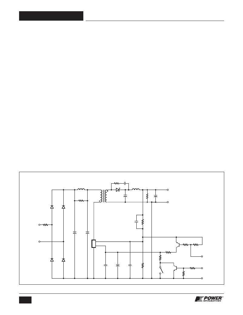
�The� circuit� shown� in� Figure� 4� is� a� typical� non-isolated� 5� V,� 300� mA�
�output� auxiliary� power� supply� using� LinkZero-AX.� Isolated�
�configurations� are� also� fully� compatible� with� the� LinkZero-AX�
�where� the� FEEDBACK� pin� receives� a� signal� from� a� primary�
�feedback/bias� winding� or� through� an� optocoupler.� The� circuit�
�of� Figure� 4� is� typical� of� auxiliary� supplies� in� white� goods� where�
�isolation� is� often� not� required.� AC� input� differential� filtering� is�
�accomplished� by� the� π� filter� formed� by� C1,� C2� and� L3.� The�
�proprietary� frequency� jitter� feature� of� the� LinkZero-AX� eliminates�
�the� need� for� any� Y� capacitor� or� common-mode� inductor.� Wire-�
�wound� resistor� RF1� is� a� fusible,� flame� proof� resistor� which� is� used�
�as� a� fuse� as� well� as� to� limit� inrush� current.� Wire� wound� types� are�
�recommended� for� designs� that� operate� >132� VAC� to� withstand�
�the� instantaneous� power� dissipated� when� AC� is� first� applied.�
�The� output� voltage� is� directly� sensed� through� feedback� resistors�
�R3� and� R9,� and� regulated� by� LinkZero-AX� (U1)� via� the� FEEDBACK�
�pin.� Capacitor� C7� provides� high� frequency� filtering� on� the�
�FEEDBACK� pin� to� filter� noise� and� to� avoid� switching� cycle� pulse�
�bunching.� The� controller� in� U1� receives� feedback� from� the�
�output� through� feedback� resistors� R9� and� R3.� Based� on� that�
�feedback,� it� enables� or� disables� the� switching� of� its� integrated�
�MOSFET� to� maintain� output� regulation.� Switching� cycles� are�
�skipped� once� the� FEEDBACK� pin� threshold� voltage� (1.70� V)� is�
�exceeded.� When� the� voltage� on� the� FEEDBACK� pin� falls� below�
�the� disable� threshold� (1.70� V),� switching� cycles� are� re-enabled.�
�By� adjusting� the� ratio� of� enabled� to� disabled� switching� cycles�
�the� output� voltage� is� regulated.� At� increased� loads,� beyond� the�
�output� peak� power� point,� where� all� switching� cycles� are�
�enabled,� the� FEEDBACK� pin� voltage� begins� to� reduce� as� the�
�power� supply� output� voltage� falls.� Under� this� condition� the�
�switching� frequency� is� also� reduced� to� limit� the� maximum� output�
�overload� power.� When� the� FEEDBACK� pin� voltage� drops� below�
�the� auto-restart� threshold� (typically� 0.9� V� on� the� FEEDBACK�
�pin),� the� power� supply� enters� the� auto-restart� mode.� In� this�
�mode,� the� power� supply� will� turn� off� for� approximately� 1.2� s� and�
�then� turn� back� on� for� approximately� 145� ms.� The� auto-restart�
�function� reduces� the� average� output� current� during� an� output�
�short-circuit� condition.�
�L3�
�1� mH�
�T1�
�3� EE16� 8�
�C4�
�R8� 220� pF�
�5.1� ?� 100� V�
�L4�
�1.8� μ� H�
�C8�
�R13� 56� μ� F�
�510� ?� 16� V�
�5� V,� 300� mA�
�D1�
�1N4007�
�D2�
�1N4007�
�R2�
�4.7� k� ?�
�1�
�10�
�D6�
�SS15�
�C6�
�220� μ� F�
�25� V�
�RTN�
�RF1�
�10� ?�
�2W�
�C9�
�330� nF�
�50� V�
�R9�
�1� k� ?�
�1%�
�85� -� 265�
�VAC�
�C1�
�3.3� μ� F�
�400� V�
�C2�
�3.3� μ� F�
�400� V�
�D�
�LinkZero-AX�
�U1�
�LNK584DG�
�FB�
�Q1�
�MMBT3904�
�D3�
�1N4007�
�D4�
�1N4007�
�S�
�BP/M�
�R16�
�750� ?�
�R11�
�100� ?�
�R12�
�20� k� ?�
�R10�
�20� k� ?�
�PD� Set�
�C5�
�150� nF�
�25� V�
�C10�
�47� μ� F�
�25� V�
�C7�
�1� nF�
�50� V�
�R3�
�511� ?�
�1%�
�SW1�
�Q2�
�MMBT3904�
�R4�
�10� k� ?�
�R14�
�2� k� ?�
�PD� Reset�
�RTN�
�PI-6121-101210�
�Figure� 4.�
�4�
�Rev.� B� 11/12�
�Schematic� of� Non-Isolated� 1.5� W,� 5� V,� 300� mA,� 0.00� W� Standby� Consumption� Power� Supply.�
�www.powerint.com�
�相关PDF资料 |
PDF描述 |
|---|---|
| GRM31CR71A475MA01L | CAP CER 4.7UF 10V 20% X7R 1206 |
| HSM36DRKH-S13 | CONN EDGECARD 72POS .156 EXTEND |
| S5AC-13-F | DIODE GPP 5A 50V SMD |
| TAP104M035CRS | CAP TANT 0.1UF 35V 20% RADIAL |
| HMM36DRKH-S13 | CONN EDGECARD 72POS .156 EXTEND |
相关代理商/技术参数 |
参数描述 |
|---|---|
| LNK586DG-TL | 功能描述:交流/直流开关转换器 5.0W @ 230 SWITCHER IC W/ 0W STANDBY RoHS:否 制造商:STMicroelectronics 输出电压:800 V 输入/电源电压(最大值):23.5 V 输入/电源电压(最小值):11.5 V 开关频率:115 kHz 电源电流:1.6 mA 工作温度范围:- 40 C to + 150 C 安装风格:SMD/SMT 封装 / 箱体:SSO-10 封装:Reel |
| LNK586GG | 功能描述:交流/直流开关转换器 5.0W @ 230 SWITCHER IC W/ 0W STANDBY RoHS:否 制造商:STMicroelectronics 输出电压:800 V 输入/电源电压(最大值):23.5 V 输入/电源电压(最小值):11.5 V 开关频率:115 kHz 电源电流:1.6 mA 工作温度范围:- 40 C to + 150 C 安装风格:SMD/SMT 封装 / 箱体:SSO-10 封装:Reel |
| LNK586GG-TL | 功能描述:交流/直流开关转换器 5.0W @ 230 SWITCHER IC W/ 0W STANDBY RoHS:否 制造商:STMicroelectronics 输出电压:800 V 输入/电源电压(最大值):23.5 V 输入/电源电压(最小值):11.5 V 开关频率:115 kHz 电源电流:1.6 mA 工作温度范围:- 40 C to + 150 C 安装风格:SMD/SMT 封装 / 箱体:SSO-10 封装:Reel |
| LNK603 | 制造商:POWERINT 制造商全称:Power Integrations, Inc. 功能描述:Energy-Efficient, Accurate CV/CC Switcher for Adapters and Chargers |
| LNK603_10 | 制造商:POWERINT 制造商全称:Power Integrations, Inc. 功能描述:Energy-Efficient, Accurate CV/CC Switcher for Adapters and Chargers |
发布紧急采购,3分钟左右您将得到回复。