- 您现在的位置:买卖IC网 > PDF目录80154 > LSM-3.3/16-D12 1-OUTPUT DC-DC REG PWR SUPPLY MODULE PDF资料下载
参数资料
| 型号: | LSM-3.3/16-D12 |
| 元件分类: | 电源模块 |
| 英文描述: | 1-OUTPUT DC-DC REG PWR SUPPLY MODULE |
| 封装: | SMT-6 |
| 文件页数: | 8/12页 |
| 文件大小: | 902K |
| 代理商: | LSM-3.3/16-D12 |
LSM-16A D12 Models
N O N - I S O L A T E D , 1 3 - 8 0 W S M T D C / D C C O N V E R T E R S
Output Overcurrent Detection
Overloading the power converter's output for an extended time will invariably
cause internal component temperatures to exceed their maximum ratings and
eventually lead to component failure. High-current-carrying components such
as inductors, FET's and diodes are at the highest risk. LSM D12 SMT Series
DC/DC converters incorporate an output overcurrent detection and shutdown
function that serves to protect both the power converter and its load.
If the output current exceeds it maximum rating by typically 70% (27 Amps)
or if the output voltage drops to less than 98% of it original value, the LSM
D12's internal overcurrent-detection circuitry immediately turns off the
converter, which then goes into a "hiccup" mode. While hiccupping, the
converter will continuously attempt to restart itself, go into overcurrent, and
then shut down. Under these conditions, the average output current will be
approximately 400mA, and the average input current will be approximately
40mA. Once the output short is removed, the converter will automatically
restart itself.
Output Voltage Trimming
Allowable trim ranges for each model in the LSM D12 SMT Series are ±10%.
Trimming is accomplished with either a trimpot or a single xed resistor. The
trimpot should be connected between +Output and Common with its wiper
connected to the Trim pin as shown in Figure 6 below.
A trimpot can be used to determine the value of a single xed resistor
which can then be connected, as shown in Figure 7, between the Trim pin
and +Output to trim down the output voltage, or between the Trim pin and
Common to trim up the output voltage. Fixed resistors should have absolute
TCR’s less than 100ppm/
°C to ensure stability.
The equations below can be starting points for selecting specic trim-resistor
values. Recall, untrimmed devices are guaranteed to be ±1.25% accurate.
Adjustment beyond the specied ±10% adjustment range is not recommended.
When using trim in combination with Remote Sense, the maximum rated power
must not be exceeded (see Remote Sense).
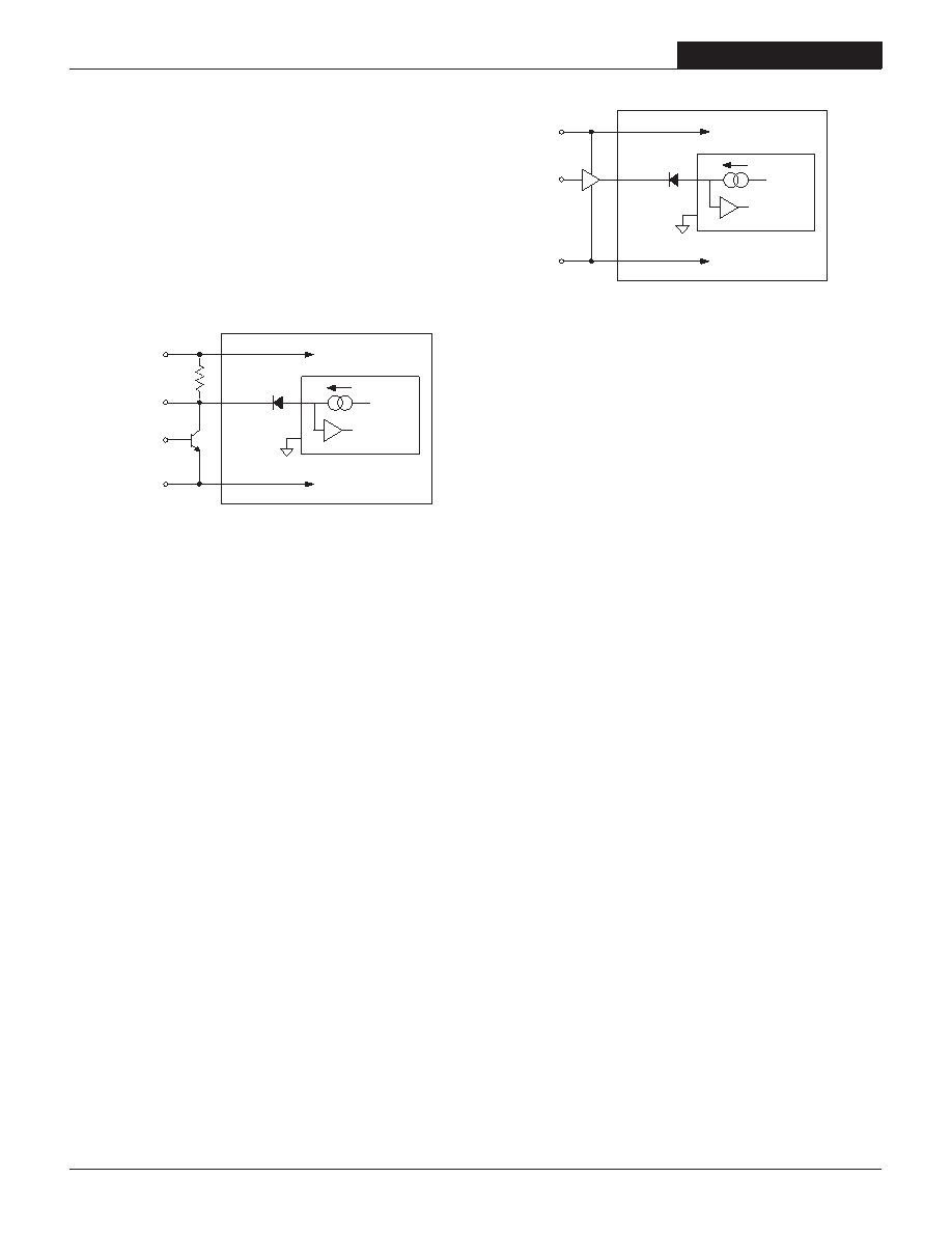
On/Off Control
The On/Off Control pin may be used for remote on/off operation. LSM D12
Series DC/DC converters are designed so that they are enabled when the
control pin is left open (open collector) and disabled when the control pin is
pulled low (to less than +0.4V relative to Common). As shown in Figure 4, all
models have an internal pull-up current source to VIN (+Input).
Dynamic control of the on/off function is best accomplished with a mechanical
relay or open-collector/open-drain drive circuit (optically isolated if appropri-
ate). The drive circuit should be able to sink appropriate current when
activated and withstand appropriate voltage when deactivated.
5
Applying an external voltage to the On/Off Control pin when no input power is
applied to the converter can cause permanent damage to the converter. The
on/off control function, however, is designed such that the converter can be
disabled (control pin pulled low) while input voltage is ramping up and then
"released" once the input has stabilized (see also power-up sequencing).
Figure 5. Inverting On/Off Control With An External CMOS Gate
Power-up sequencing
If a controlled start-up of one or more LSM D12 Series DC/DC converters
is required, or if several output voltages need to be powered-up in a given
sequence, the On/Off control pin can be driven with an external open collec-
tor device as per Figure 4.
Leaving the input of the on/off circuit closed during power-up will have the
output of the DC/DC converter disabled. When the input to the external open
collector is pulled high, the DC/DC converter's output will be enabled.
Output Overvoltage Protection
LSM D12 SMT Series DC/DC converters do not incorporate output overvolt-
age protection. In the extremely rare situation in which the device’s feedback
loop is broken, the output voltage may run to excessively high levels (VOUT =
VIN). If it is absolutely imperative that you protect your load against any and
all possible overvoltage situations, voltage limiting circuitry must be provided
external to the power converter.
Figure 4. On/Off Control Using An External Open Collector Driver
相关PDF资料 |
PDF描述 |
|---|---|
| L8115L-R20-R | SPECIALTY ANALOG CIRCUIT, PDSO20 |
| LMD28SP | 1-OUTPUT 75 W DC-DC REG PWR SUPPLY MODULE |
| LH0070-1H-MIL | 1-OUTPUT THREE TERM VOLTAGE REFERENCE, 10 V, MBCY3 |
| LS4301-9PD3T | 1-OUTPUT 100 W AC-DC PWR FACTOR CORR MODULE |
| LS1601-9ERD1T | 1-OUTPUT 100 W AC-DC REG PWR SUPPLY MODULE |
相关代理商/技术参数 |
参数描述 |
|---|---|
| LSM331M2C---2225S | 制造商:Surge Components Inc 功能描述:CAP ALUM 330UF 160V ?20% 3000LHRS 22 X 25 - Bulk |
| LSM331M2D---2230S | 制造商:Surge Components Inc 功能描述:CAP ALUM 330UF 200V ?20% 3000LHRS 22 X 30 - Bulk |
| LSM331M2D---2525S | 制造商:Surge Components Inc 功能描述:CAP ALUM 330UF 200V ?20% 3000LHRS 25 X 25 - Bulk |
| LSM331M2E---2240S | 制造商:Surge Components Inc 功能描述:CAP ALUM 330UF 250V ?20% 3000LHRS 22 X 40 - Bulk |
| LSM331M2E---2530S | 制造商:Surge Components Inc 功能描述:CAP ALUM 330UF 250V ?20% 3000LHRS 25 X 30 - Bulk |
发布紧急采购,3分钟左右您将得到回复。