- 您现在的位置:买卖IC网 > PDF目录80258 > LSP3100C18D (LITE-ON SEMICONDUCTOR CORP) 1.5 A SWITCHING REGULATOR, 1800 kHz SWITCHING FREQ-MAX, PDSO5 PDF资料下载
参数资料
| 型号: | LSP3100C18D |
| 厂商: | LITE-ON SEMICONDUCTOR CORP |
| 元件分类: | 稳压器 |
| 英文描述: | 1.5 A SWITCHING REGULATOR, 1800 kHz SWITCHING FREQ-MAX, PDSO5 |
| 封装: | SOT-23, 5 PIN |
| 文件页数: | 12/12页 |
| 文件大小: | 368K |
| 代理商: | LSP3100C18D |
Liteon Semiconductor Corporation
LSP3100
1.5MHZ, 800mA Synchronous Step-Down Converter
Rev1.3
9/12
APPLICATION INFORMATION
R2
316K
R1
2
C3
10F
5
3
4
1
Vout 1.8V
GND
VFB
SW
Run
2.2H
Vin 2.7V-4.2V
L1
22pF
C2
C1
4.7F
632K
Vin
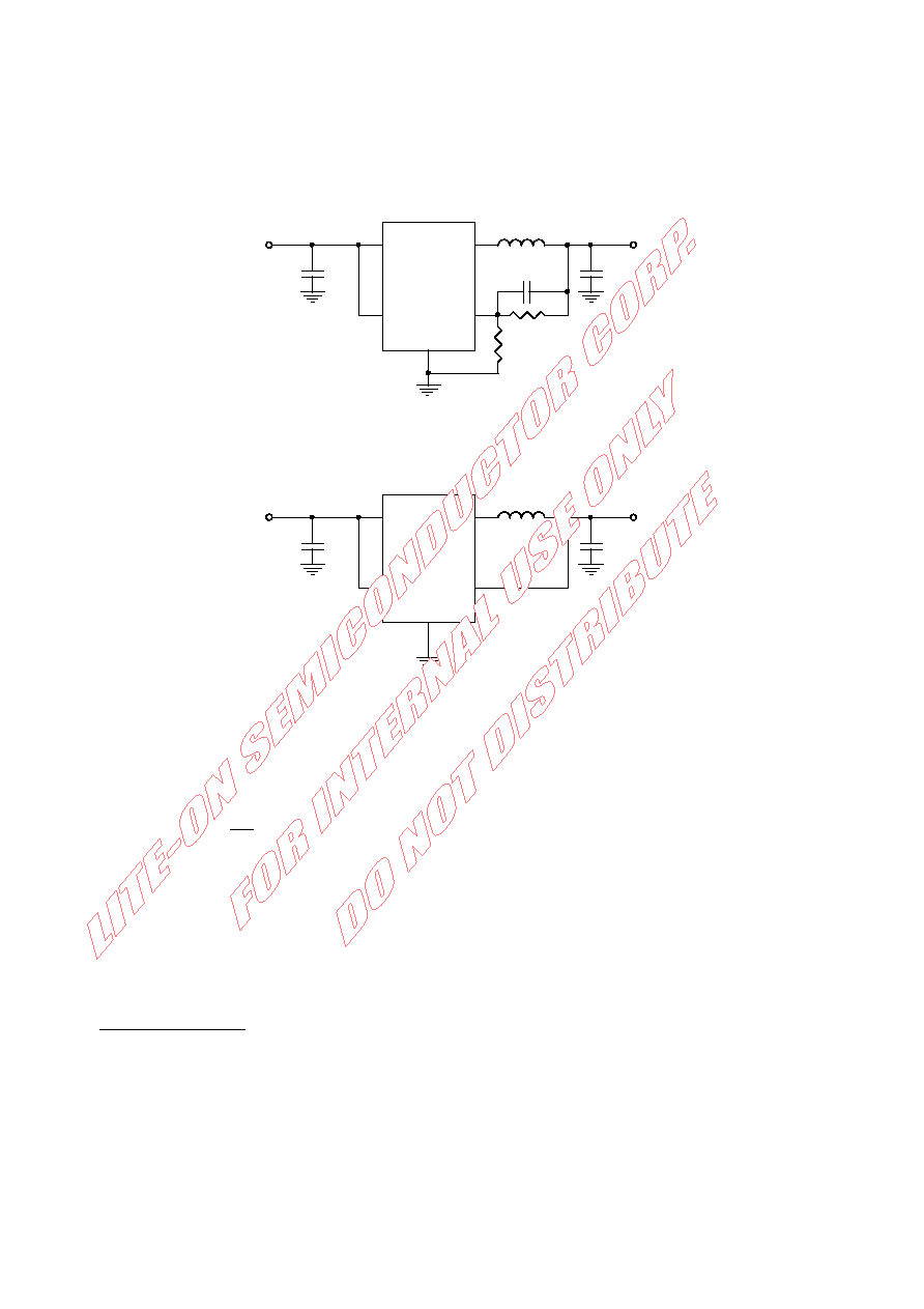
Fig.1 Basic Application Circuit with LSP3100 adjustable version
2
C3
10F
5
3
4
1
Vout 1.8V
GND
VOUT
SW
Run
2.2H
Vin 2.5V-5.5V
L1
C1
4.7F
Vin
Fig.2 Basic Application Circuit with fixed output versions
SETTING THE OUTPUT VOLTAGE
Figure 1 above shows the basic application circuit with LSP3100 adjustable output version. The external resistor
sets the output voltage according to the following equation:
+
×
=
2
1
OUT
R
1
V
6
.
0
V
For example, fixed R1=300k for all outputs; R2=300k for VOUT=1.2V, R2=200k for VOUT=1.5V, R2=150k for
VOUT=1.8V and R2=95.3k for VOUT=2.5V.
INDUCTOR SELECTION
For most designs, the LSP3100 operates with inductors of 1H to 4.7H. Low inductance values are physically
smaller but require faster switching, which results in some efficiency loss. The inductor value can be derived from
the following equation:
()
OUT
IN
OUT
IN
L
OSC
VV
V
L
VI
f
×
=
× ×
Where IL is inductor Ripple Current. Large value inductors lower ripple current and small value inductors result in
high ripple currents. Choose inductor ripple current approximately 35% of the maximum load current 800mA, or
IL=280mA.
For output voltages above 2.0V, when light-load efficiency is important, the minimum recommended inductor is
2.2H. For optimum voltage-positioning load transients, choose an inductor with DC series resistance in the 50m
to 150m range. For higher efficiency at heavy loads (above 200mA), or minimal load regulation (but some transient
overshoot), the resistance should be kept below 100m. The DC current rating of the inductor should be at least
equal to the maximum load current plus half the ripple current to prevent core saturation (800mA+140mA). Table 1
lists some typical surface mount inductors that meet target applications for the LSP3100.
相关PDF资料 |
PDF描述 |
|---|---|
| LM185AXH-2.5 | 1-OUTPUT TWO TERM VOLTAGE REFERENCE, 2.5 V, MBCY2 |
| LFB5.2S | 1-OUTPUT 50 W DC-DC REG PWR SUPPLY MODULE |
| LFB48S | 1-OUTPUT 75 W DC-DC REG PWR SUPPLY MODULE |
| LM4040BEM3-2.5X | 1-OUTPUT TWO TERM VOLTAGE REFERENCE, 2.5 V, PDSO3 |
| LS4601-7ERD4T | 1-OUTPUT 100 W AC-DC PWR FACTOR CORR MODULE |
相关代理商/技术参数 |
参数描述 |
|---|---|
| LSP32-K2-RGBA | 制造商:Dialight 功能描述:LED MODULE 32X K2 RGBA |
| LSP-32K2-RGBW | 制造商:Dialight 功能描述: |
| LSP32-K2-RGBW | 制造商:Dialight 功能描述:LED MODULE 32X K2 RGBW |
| LSP-32K2-WWWW | 制造商:Dialight 功能描述: |
| LSP32-K2-WWWW | 制造商:Dialight 功能描述:LED MODULE 32X K2 WWWW |
发布紧急采购,3分钟左右您将得到回复。