- 您现在的位置:买卖IC网 > PDF目录44976 > LSP3102Y18AD (LITE-ON SEMICONDUCTOR CORP) 1.45 A SWITCHING REGULATOR, 1800 kHz SWITCHING FREQ-MAX, PDSO5 PDF资料下载
参数资料
| 型号: | LSP3102Y18AD |
| 厂商: | LITE-ON SEMICONDUCTOR CORP |
| 元件分类: | 稳压器 |
| 英文描述: | 1.45 A SWITCHING REGULATOR, 1800 kHz SWITCHING FREQ-MAX, PDSO5 |
| 封装: | SOT-89, 5 PIN |
| 文件页数: | 4/9页 |
| 文件大小: | 179K |
| 代理商: | LSP3102Y18AD |
Liteon Semiconductor Corporation
LSP3102
1A Synchronous Step-Down Converter
Rev1.1
4/9
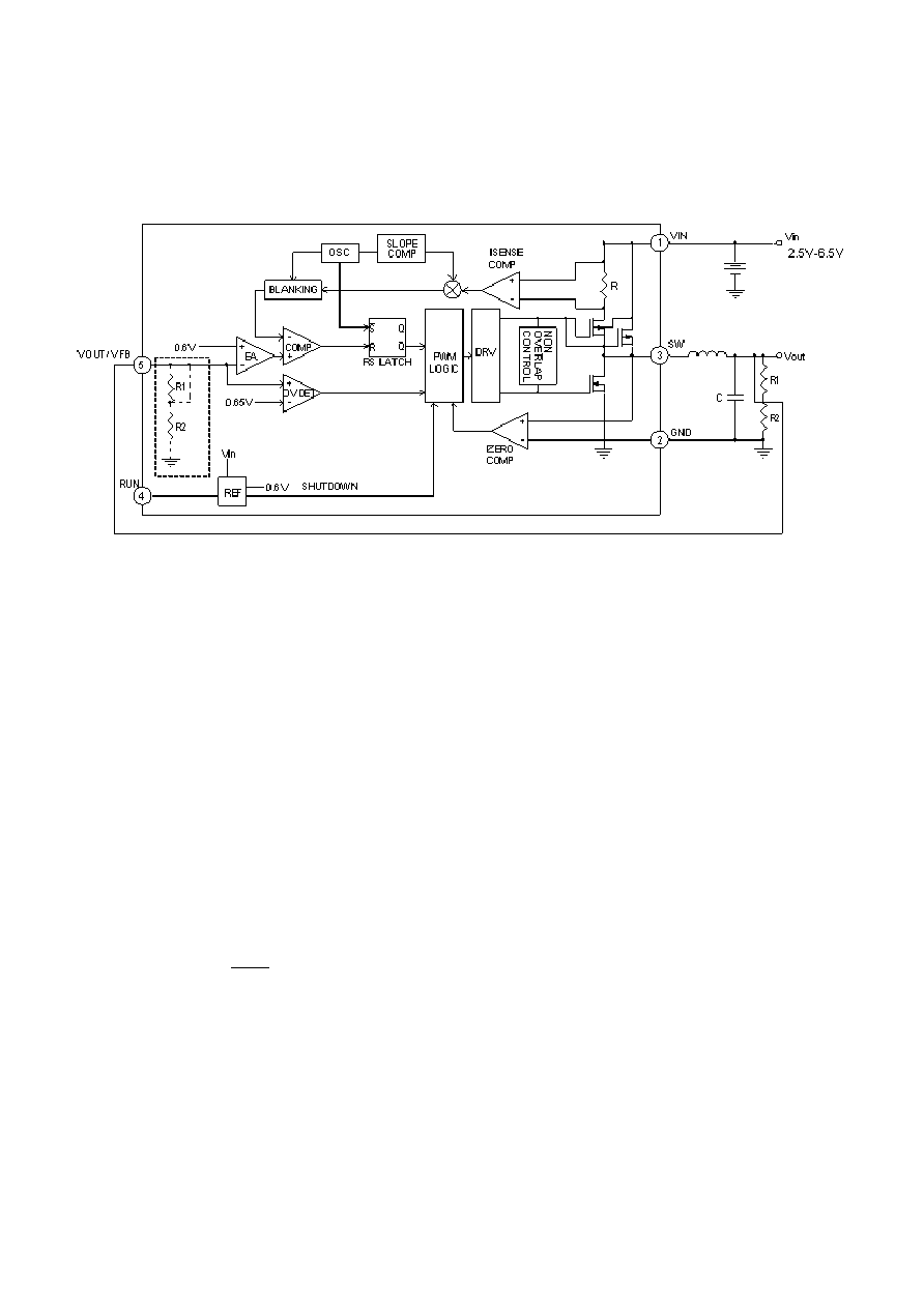
FUNCTIONAL BLOCK DIAGRAM
*
Note: For adjustable output, R1and R2 is external.
FUNCTIONAL DESCRIPTION
CONTROL SCHEME
The LSP3102 utilizes a fixed-frequency, current-mode PWM control scheme combined with fully-integrated power
MOSFETs to produce a compact and efficient step-down DC-DC solution. During normal operation the high-side
MOSFET turns on each cycle and remains on until the current comparator turns it off. At this point the low-side
MOSFET turns on and remains on until either the end of the switching cycle or until the inductor current approaches
zero. The error amplifier adjusts the current comparator's threshold as necessary in order to ensure that the output
voltage remains in regulation.
LIGHT LOAD POWER SAVING OPERATION
When operating under light-load conditions, the LSP3102 enters pulse skipping mode. Under light load conditions the
LSP3102 reduces its switching frequency in order to achieve high efficiency. The bottom MOSFET is turned off by the
current comparator, the switch voltage will ring, this is discontinuous mode operation, and is normal behavior for the
switching regulator.
DROPOUT OPERATION
When the input voltage decreases toward the value of the output voltage, the LSP3102 allows the main switch to
remain on for more than one switching cycle and increases the duty cycle until it reaches 100%.
The duty cycle D of a step-down converter is defined as:
OUT
ON
OSC
IN
V
D=T
f
100%
V
××
≈
×
Where TON is the main switch on time and fOSC is the oscillator frequency (1.5MHz).
The output voltage then is the input voltage minus the voltage drop across the main switch and the inductor. At low
input supply voltage, the RDS(ON) of the P-Channel MOSFET increase, and the efficiency of the converter decreases.
Caution must be exercised to ensure the heat dissipated not to exceed the maximum junction temperature of the IC.
MAXIMUM LOAD CURRENT
The LSP3102 will operate with input supply voltages as low as 2.5V, however, the maximum load current decreases
at lower input due to large IR drop on the main switch and synchronous rectifier. The slope compensation signal
reduces the peak inductor current as a function of the duty cycle to prevent sub harmonic oscillations at duty cycles
greater than 50%. Conversely the current limit increases as the duty cycle decreases.
相关PDF资料 |
PDF描述 |
|---|---|
| LSP3102Q18AD | 1.45 A SWITCHING REGULATOR, 1800 kHz SWITCHING FREQ-MAX, QCC16 |
| LSP3112LAD | SWITCHING REGULATOR, PDSO10 |
| LSP3123T50AE | 7.5 A SWITCHING REGULATOR, 173 kHz SWITCHING FREQ-MAX, SFM5 |
| LSP3123T12AE | 7.5 A SWITCHING REGULATOR, 173 kHz SWITCHING FREQ-MAX, SFM5 |
| LSP3123TAE | 7.5 A SWITCHING REGULATOR, 173 kHz SWITCHING FREQ-MAX, SFM5 |
相关代理商/技术参数 |
参数描述 |
|---|---|
| LSP32-K2-RGBA | 制造商:Dialight 功能描述:LED MODULE 32X K2 RGBA |
| LSP-32K2-RGBW | 制造商:Dialight 功能描述: |
| LSP32-K2-RGBW | 制造商:Dialight 功能描述:LED MODULE 32X K2 RGBW |
| LSP-32K2-WWWW | 制造商:Dialight 功能描述: |
| LSP32-K2-WWWW | 制造商:Dialight 功能描述:LED MODULE 32X K2 WWWW |
发布紧急采购,3分钟左右您将得到回复。