- 您现在的位置:买卖IC网 > PDF目录67127 > LSS-T/10-W12-C (MURATA POWER SOLUTIONS INC) 1-OUTPUT 60 W DC-DC REG PWR SUPPLY MODULE PDF资料下载
参数资料
| 型号: | LSS-T/10-W12-C |
| 厂商: | MURATA POWER SOLUTIONS INC |
| 元件分类: | 电源模块 |
| 英文描述: | 1-OUTPUT 60 W DC-DC REG PWR SUPPLY MODULE |
| 封装: | ROHS COMPLIANT, SIP-5 |
| 文件页数: | 4/8页 |
| 文件大小: | 603K |
| 代理商: | LSS-T/10-W12-C |
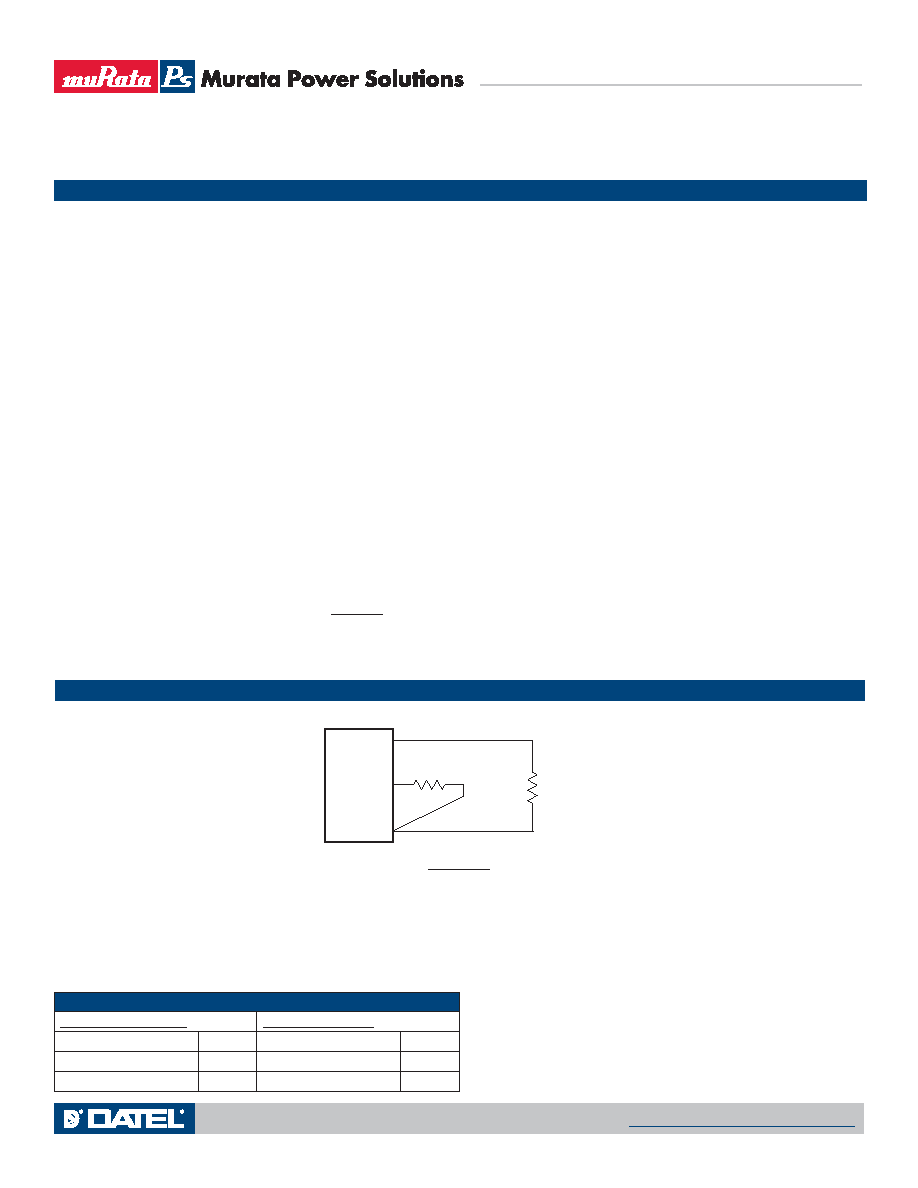
Trim Connections
RTRIM
RLOAD
Trim
+VOUT
Ground
RTRIM (kΩ) =
1.182
VOUT 0.591
(1) All models are tested and specied with external 1||10 μF ceramic/tantalum output
capacitors and a 22 μF external input capacitor. All capacitors are low ESR types. These
capacitors are necessary to accommodate our test equipment and may not be required
to achieve specied performance in your applications. All models are stable and regulate
within spec under no-load conditions.
All specications are typical unless noted. General conditions for Specications are
+25 °C, VIN=nominal, VOUT=5V, full load. Adequate airow must be supplied for extended
testing under power.
(2) Input Ripple Current is tested and specied over a 5 Hz to 20 MHz bandwidth. Input lter-
ing is CIN=2 × 100 μF, 100V tantalum, CBUS=1000 μF, 100V electrolytic, LBUS=1 μH.
(3) Note that Maximum Power Derating curves indicate an average current at nominal input
voltage. At higher temperatures and/or lower airow, the DC/DC converter will tolerate
brief full current outputs if the total RMS current over time does not exceed the Derating
curve. All Derating curves are presented at sea level altitude. Be aware of reduced power
dissipation with increasing density altitude.
(4) Mean Time Before Failure is calculated using the Telcordia (Belcore) SR-332 Method 1,
Case 3, ground xed conditions, Tpcboard=+25°C, full output load, natural air convec-
tion.
(5) The On/Off Control is normally controlled by a switch or open collector or open drain tran-
sistor. But it may also be driven with external logic or by applying appropriate external
voltages which are referenced to Input Common.
(6) Short circuit shutdown begins when the output voltage degrades approximately 2% from
the selected setting.
(7) The outputs are not intended to sink appreciable reverse current. This may damage the
outputs.
(8) Output noise may be further reduced by adding an external lter. See I/O Filtering and
Noise Reduction. Use only as much output ltering as needed and no more. Larger caps
may slow transient response or degrade dynamic performance. Thoroughly test your
system under full load, especially with low-ESR ceramic capacitors.
(9) All models are fully operational and meet published specications, including “cold start” at
–40°C.
(10) Regulation specications describe the deviation as the line input voltage or output load
current is varied from a nominal midpoint value to either extreme.
(11) For the LSS-T/10-W12, the maximum rated output power is 51 Watts (5.1 Volts and
10 Amps). Output adjustment up to 6 Volts must reduce current to remain within the
51 Watt output limit.
(12) Output current limit and short circuit protection is non-latching. When the overcurrent
fault is removed, the converter will immediately recover.
(13) Do not exceed maximum power specications when adjusting the output trim.
(14) At zero output current, the output may contain low frequency components which exceed
the ripple specication. The output may be operated indenitely with no load.
(15) Input Fusing: If reverse polarity is accidentally applied to the input, a body diode will
become forward biased and will conduct considerable current. To ensure reverse input
protection with full output load, always connect an external input fast-blow fuse in series
with the +VIN input. Use approximately twice the full input current rating with nominal
input voltage.
(16) “Hiccup” overcurrent operation repeatedly attempts to restart the converter with a brief,
full-current output. If the overcurrent condition still exists, the restart current will be
removed and then tried again. This short current pulse prevents overheating and damag-
ing the converter. Once the fault is removed, the converter immediately recovers normal
operation.
(17) Output accuracy is dependent on user-supplied trim resistors. To achieve high accuracy,
use ±1% or better tolerance metal-lm resistors.
(18) At full power, on-board component package temperatures must not exceed +128
°C.
(19) VIN must be 2 Volts or higher than VOUT for +3.3 to +5V outputs.
Notes
Soldering Guidelines
Murata Power Solutions recommends the specications below when installing these converters. These specications vary depending on the solder type. Exceeding these specica-
tions may cause damage to the product. Be cautious when there is high atmospheric humidity. We strongly recommend a mild pre-bake (100° C. for 30 minutes). Your production
environment may differ; therefore please thoroughly review these guidelines with your process engineers.
Wave Solder Operations for through-hole mounted products (THMT)
For Sn/Ag/Cu based solders:
For Sn/Pb based solders:
Maximum Preheat Temperature
115° C.
Maximum Preheat Temperature
105° C.
Maximum Pot Temperature
270° C.
Maximum Pot Temperature
250° C.
Maximum Solder Dwell Time
7 seconds
Maximum Solder Dwell Time
6 seconds
LSS-T/10-W12
Adjustable Output 10 Amp SIP-mount DC/DC Converter
MDC_MDC_LSS-T10-W12.A06 Page 4 of 8
www.murata-ps.com/support
相关PDF资料 |
PDF描述 |
|---|---|
| LV5106FN | SPECIALTY ANALOG CIRCUIT, QCC48 |
| LV59001M | 1-CHANNEL POWER SUPPLY SUPPORT CKT, PDSO8 |
| LV59025M | 1-CHANNEL POWER SUPPLY SUPPORT CKT, PDSO8 |
| LV8549M | STEPPER MOTOR CONTROLLER, PDSO10 |
| M115-8 | 1000 MHz, OTHER CLOCK GENERATOR, DIP24 |
相关代理商/技术参数 |
参数描述 |
|---|---|
| LSST670 | 制造商:INFINEON 制造商全称:Infineon Technologies AG 功能描述:Multi TOPLED |
| LSST670-JO | 制造商:INFINEON 制造商全称:Infineon Technologies AG 功能描述:Multi TOPLED |
| LSST672 | 制造商:INFINEON 制造商全称:Infineon Technologies AG 功能描述:Super Multi TOPLED High-Current LED |
| LSST672-NO | 制造商:INFINEON 制造商全称:Infineon Technologies AG 功能描述:Super Multi TOPLED High-Current LED |
| LSSTOP-72 | 制造商:LISTA 功能描述:Stainless Steel Over Wood Top 72x30 |
发布紧急采购,3分钟左右您将得到回复。