参数资料
| 型号: | LT1033CT |
| 厂商: | Linear Technology |
| 文件页数: | 5/12页 |
| 文件大小: | 0K |
| 描述: | IC REG LDO NEG ADJ TO220-3 |
| 标准包装: | 50 |
| 稳压器拓扑结构: | 负,可调式 |
| 输出电压: | -1.2 V ~ -32 V |
| 稳压器数量: | 1 |
| 电流 - 限制(最小): | 3A |
| 工作温度: | 0°C ~ 125°C |
| 安装类型: | 通孔 |
| 封装/外壳: | TO-220-3 |
| 供应商设备封装: | TO-220-3 |
| 包装: | 管件 |
�� �
�
�LT1033�
�APPLICATIO� N� S� I� N� FOR� M� ATIO� N�
�?� +� I� ADJ� (� R� 2� )�
�V� OUT� =� V� REF� ?� 1� +�
�R� 2� =�
�–� I� ADJ�
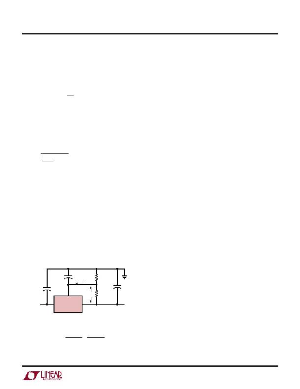
�Output Voltage�
�The� output� voltage� is� determined� by� two� external� resis-�
�tors,� R1� and� R2� (see� Figure� 1).� The� exact� formula� for� the�
�output� voltage� is:�
�?� R� 2� ?�
�?� R� 1� ?�
�Where:� V� REF� =� Reference� Voltage,� I� ADJ� =� Adjustment� Pin�
�Current.� In� most� applications,� the� second� term� is� small�
�enough� to� be� ignored,� typically� about� 0.5%� of� V� OUT� .� In�
�more� critical� applications,� the� exact� formula� should� be�
�used,� with� I� ADJ� equal� to� 65� μ� A.� Solving� for� R2� yields:�
�V� OUT� – V� REF�
�V� REF�
�R� 1�
�Smaller� values� of� R1� and� R2� will� reduce� the� influence� of�
�I� ADJ� on� the� output� voltage,� but� the� no-load� current� drain� on�
�the� regulator� will� be� increased.� Typical� values� for� R1� are�
�between� 100� ?� and� 300� ?� ,� giving� 12.5mA� and� 4.2mA�
�no-load� current� respectively.� There� is� an� additional� con-�
�sideration� in� selecting� R1,� the� minimum� load� current�
�specification� of� the� regulator.� The� operating� current� of� the�
�LT1033� flows� from� input� to� output.� If� this� current� is� not�
�absorbed� by� the� load,� the� output� of� the� regulator� will� rise�
�above� the� regulated� value.� The� current� drawn� by� R1� and� R2�
�is� normally� high� enough� to� absorb� the� current,� but� care�
�must� be� taken� in� no-load� situations� where� R1� and� R2� have�
�high� values.� The� maximum� value� for� the� operating� current,�
�which� must� be� absorbed,� is� 5mA� for� the� LT1033.� If� input-�
�output� voltage� differential� is� less� than� 10V,� the� operating�
�current� that� must� be� absorbed� drops� to� 3mA.�
�Capacitors� and� Protection� Diodes�
�An� output� capacitor,� C3,� is� required� to� provide� proper�
�frequency� compensation� of� the� regulator� feedback� loop.�
�A� 2� μ� F� or� larger� solid� tantalum� capacitor� is� generally�
�sufficient� for� this� purpose� if� the� 1MHz� impedance� of� the�
�capacitor� is� 1� ?� or� less.� High� Q� capacitors,� such� as� Mylar,�
�are� not� recommended� because� their� extremely� low� ESR�
�(effective� series� resistance)� can� drastically� reduce� phase�
�margin.� When� these� types� of� capacitors� must� be� used�
�because� of� other� considerations,� add� a� 0.5� ?� carbon�
�resistor� in� series� with� 1� μ� F.� Aluminum� electrolytic� capaci-�
�tors� may� be� used,� but� the� minimum� value� should� be� 25� μ� F�
�to� ensure� a� low� impedance� at� 1MHz.� The� output� capacitor�
�should� be� located� within� a� few� inches� of� the� regulator� to�
�keep� lead� impedance� to� a� minimum.� The� following� caution�
�should� be� noted:� if� the� output� voltage� is� greater� than� 6V�
�and� an� output� capacitor� greater� than� 20� μ� F� has� been� used,�
�it� is� possible� to� damage� the� regulator� if� the� input� voltage�
�becomes� shorted,� due� to� the� output� capacitor� discharging�
�into� the� regulator.� This� can� be� prevented� by� using� diode� D1�
�(see� Figure� 2)� between� the� input� and� the� output.�
�The� input� capacitor,� C2,� is� only� required� if� the� regulator� is�
�more� than� 4� inches� from� the� raw� supply� filter� capacitor.�
�Bypassing� the� Adjustment� Pin�
�The� adjustment� pin� of� the� LT1033� may� be� bypassed� with�
�+�
�C2�
�5� μ� F�
�+�
�ADJ�
�C1�
�10� μ� F�
�I� ADJ�
�V� REF�
�R2�
�R1�
�+�
�C3�
�2� μ� F�
�a� capacitor� to� ground,� C1,� to� reduce� output� ripple,� noise,�
�and� impedance.� These� parameters� scale� directly� with�
�output� voltage� if� the� adjustment� pin� is� not� bypassed.� A�
�bypass� capacitor� reduces� ripple,� noise� and� impedance� to�
�that� of� a� 1.25V� regulator.� In� a� 15V� regulator� for� example,�
�–V� IN�
�V� IN�
�V� OUT�
�–V� OUT�
�these� parameters� are� improved� by� 15V/1.25V� =� 12� to� 1.�
�=� =� 704� ?�
�V� OUT� –� V� REF� 10V� –� 1.25V�
�–� 65� μ� A�
�100� ?�
�–� I� ADJ�
�LT1033�
�LT1033� ?� F01�
�EXAMPLE:�
�1.� A� PRECISION� 10V� REGULATOR� TO� SUPPLY� UP� TO� 3A� LOAD� CURRENT.�
�A.� SELECT� R1� =� 100� ?� TO� MINIMIZE� EFFECT� OF� I� ADJ�
�B.� CALCULATE� R2� =�
�V� REF� 1.25V�
�R1�
�This� improvement� holds� only� for� those� frequencies� where�
�the� impedance� of� the� bypass� capacitor� is� less� than� R1.� Ten�
�microfarads� is� generally� sufficient� for� 60Hz� power� line�
�applications� where� the� ripple� frequency� is� 120Hz,� since�
�X� C� =� 130� ?� .� The� capacitor� should� have� a� voltage� rating� at�
�least� as� high� as� the� output� voltage� of� the� regulator.� Values�
�Figure� 1�
�1033fc�
�5�
�相关PDF资料 |
PDF描述 |
|---|---|
| LT1118CS8 | IC REG LDO ADJ .8A 8SOIC |
| LT1963AET-3.3#06PBF | IC REG LDO 3.3V 1.5A TO220-5 |
| GSC43DREF-S734 | CONN EDGECARD 86POS .100 EYELET |
| AMM08DTAI-S189 | CONN EDGECARD 16POS R/A .156 SLD |
| GMC43DREF-S734 | CONN EDGECARD 86POS .100 EYELET |
相关代理商/技术参数 |
参数描述 |
|---|---|
| LT1033CT#PBF | 功能描述:IC REG LDO NEG ADJ TO220-3 RoHS:否 类别:集成电路 (IC) >> PMIC - 稳压器 - 线性 系列:- 标准包装:800 系列:- 稳压器拓扑结构:正,固定式 输出电压:2.5V 输入电压:最高 16V 电压 - 压降(标准):0.7V @ 4A 稳压器数量:1 电流 - 输出:4A 电流 - 限制(最小):4.2A 工作温度:0°C ~ 125°C 安装类型:表面贴装 封装/外壳:TO-263-6,D²Pak(5 引线+接片),TO-263BA 供应商设备封装:TO-263-5 包装:带卷 (TR) 其它名称:AP1184K525L-13AP1184K525LDITR |
| LT1033MK | 制造商:Linear Technology 功能描述:Standard Regulator Neg -1.2V to -32V 3A 3-Pin(2+Tab) TO-3 |
| LT1033MK/883 | 制造商:Linear Technology 功能描述:Standard Regulator Neg -1.2V to -32V 3A 3-Pin(2+Tab) TO-3 |
| LT1034BCZ-1.2 | 功能描述:IC VREF SHUNT PREC DUAL TO-92-3 RoHS:否 类别:集成电路 (IC) >> PMIC - 电压基准 系列:- 产品培训模块:Voltage Reference Basics 标准包装:100 系列:- 基准类型:旁路,精度 输出电压:4.096V 容差:±0.075% 温度系数:50ppm/°C 输入电压:- 通道数:1 电流 - 阴极:1µA 电流 - 静态:- 电流 - 输出:10mA 工作温度:0°C ~ 70°C 安装类型:表面贴装 封装/外壳:8-SOIC(0.154",3.90mm 宽) 供应商设备封装:8-SOIC 包装:管件 |
| LT1034BCZ-1.2#PBF | 功能描述:IC VREF SHUNT PREC DUAL TO-92-3 RoHS:是 类别:集成电路 (IC) >> PMIC - 电压基准 系列:- 产品培训模块:Voltage Reference Basics 标准包装:100 系列:- 基准类型:旁路,精度 输出电压:4.096V 容差:±0.075% 温度系数:50ppm/°C 输入电压:- 通道数:1 电流 - 阴极:1µA 电流 - 静态:- 电流 - 输出:10mA 工作温度:0°C ~ 70°C 安装类型:表面贴装 封装/外壳:8-SOIC(0.154",3.90mm 宽) 供应商设备封装:8-SOIC 包装:管件 |
发布紧急采购,3分钟左右您将得到回复。