- 您现在的位置:买卖IC网 > PDF目录44978 > LT1054CDWRE4 (TEXAS INSTRUMENTS INC) SWITCHED CAPACITOR REGULATOR, 35 kHz SWITCHING FREQ-MAX, PDSO16 PDF资料下载
参数资料
| 型号: | LT1054CDWRE4 |
| 厂商: | TEXAS INSTRUMENTS INC |
| 元件分类: | 稳压器 |
| 英文描述: | SWITCHED CAPACITOR REGULATOR, 35 kHz SWITCHING FREQ-MAX, PDSO16 |
| 封装: | GREEN, PLASTIC, SOIC-16 |
| 文件页数: | 29/30页 |
| 文件大小: | 607K |
| 代理商: | LT1054CDWRE4 |
第1页第2页第3页第4页第5页第6页第7页第8页第9页第10页第11页第12页第13页第14页第15页第16页第17页第18页第19页第20页第21页第22页第23页第24页第25页第26页第27页第28页当前第29页第30页
LT1054
SWITCHED-CAPACITOR VOLTAGE CONVERTERS
WITH REGULATORS
SLVS033F FEBRUARY 1990 REVISED NOVEMBER 2004
8
POST OFFICE BOX 655303
DALLAS, TEXAS 75265
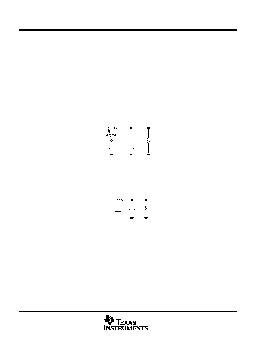
PRINCIPLES OF OPERATION
A review of a basic switched-capacitor building block is helpful in understanding the operation of the LT1054. When
the switch shown in Figure 12 is in the left position, capacitor C1 charges to the voltage at V1. The total charge on
C1 is q1 = C1V1. When the switch is moved to the right, C1 is discharged to the voltage at V2. After this discharge
time, the charge on C1 is q2 = C1V2. The charge has been transferred from the source V1 to the output V2. The
amount of charge transferred is shown in equation 1.
Dq + q1 * q2 + C1(V1 * V2)
If the switch is cycled f times per second, the charge transfer per unit time (i.e., current) is as shown in equation 2.
I
+ f
Dq + f
C1(1
* V2)
To obtain an equivalent resistance for a switched-capacitor network, this equation can be rewritten in terms of voltage
and impedance equivalence as shown in equation 3.
I
+ V1 * V2
1 fC1
+ V1 * V2
R
EQUIV
C2
C1
V2
f
V1
RL
Figure 12. Switched-Capacitor Building Block
A new variable, REQUIV, is defined as REQUIV = 1 ÷ fC1. The equivalent circuit for the switched-capacitor network is
shown in Figure 13. The LT1054 has the same switching action as the basic switched-capacitor building block. Even
though this simplification does not include finite switch-on resistance and output-voltage ripple, it provides an insight
into how the device operates.
C2
V2
V1
RL
REQUIV
R
EQUIV +
1
fC1
Figure 13. Switched-Capacitor Equivalent Circuit
These simplified circuits explain voltage loss as a function of oscillator frequency (see Figure 7). As oscillator
frequency is decreased, the output impedance eventually is dominated by the 1/fC1 term, and voltage losses rise.
Voltage losses also rise as oscillator frequency increases. This is caused by internal switching losses that occur due
to some finite charge being lost on each switching cycle. This charge loss per-unit-cycle, when multiplied by the
switching frequency, becomes a current loss. At high frequency, this loss becomes significant and voltage losses
again rise.
The oscillator of the LT1054 is designed to operate in the frequency band where voltage losses are at a minimum.
(1)
(2)
(3)
相关PDF资料 |
PDF描述 |
|---|---|
| LT1054IPE4 | SWITCHED CAPACITOR REGULATOR, 35 kHz SWITCHING FREQ-MAX, PDIP8 |
| LT1054MJ8/883 | SWITCHED CAPACITOR REGULATOR, 25 kHz SWITCHING FREQ-MAX, CDIP8 |
| 5962-8956201PX | SWITCHED CAPACITOR REGULATOR, 25 kHz SWITCHING FREQ-MAX, CDIP8 |
| 5962-8956201PA | SWITCHED CAPACITOR REGULATOR, 25 kHz SWITCHING FREQ-MAX, CDIP8 |
| 5962-8956201XX | SWITCHED CAPACITOR REGULATOR, 40 kHz SWITCHING FREQ-MAX, MBCY8 |
相关代理商/技术参数 |
参数描述 |
|---|---|
| LT1054CDWRG4 | 功能描述:电荷泵 Swed-Capacitor Vltg Converters RoHS:否 制造商:Maxim Integrated 功能:Inverting, Step Up 输出电压:- 1.5 V to - 5.5 V, 3 V to 11 V 输出电流:100 mA 电源电流:1 mA 最大工作温度:+ 70 C 封装 / 箱体:SOIC-8 Narrow 封装:Tube |
| LT1054CN8 | 功能描述:IC REG SWITCHED CAP DBL INV 8DIP RoHS:否 类别:集成电路 (IC) >> PMIC - 稳压器 - DC DC 开关稳压器 系列:- 标准包装:2,500 系列:- 类型:升压(升压) 输出类型:可调式 输出数:1 输出电压:1.24 V ~ 30 V 输入电压:1.5 V ~ 12 V PWM 型:电流模式,混合 频率 - 开关:600kHz 电流 - 输出:500mA 同步整流器:无 工作温度:-40°C ~ 85°C 安装类型:表面贴装 封装/外壳:8-SOIC(0.154",3.90mm 宽) 包装:带卷 (TR) 供应商设备封装:8-SOIC |
| LT1054CN8#PBF | 功能描述:IC REG SWITCHED CAP DBL INV 8DIP RoHS:是 类别:集成电路 (IC) >> PMIC - 稳压器 - DC DC 开关稳压器 系列:- 标准包装:250 系列:- 类型:降压(降压) 输出类型:固定 输出数:1 输出电压:1.2V 输入电压:2.05 V ~ 6 V PWM 型:电压模式 频率 - 开关:2MHz 电流 - 输出:500mA 同步整流器:是 工作温度:-40°C ~ 85°C 安装类型:表面贴装 封装/外壳:6-UFDFN 包装:带卷 (TR) 供应商设备封装:6-SON(1.45x1) 产品目录页面:1032 (CN2011-ZH PDF) 其它名称:296-25628-2 |
| LT1054CN8PBF | 制造商:Linear Technology 功能描述:DC-DC converter,LT1054CN8 -Vin/2Vin 20mA |
| LT1054CP | 功能描述:电荷泵 Bipolar Regulated V RoHS:否 制造商:Maxim Integrated 功能:Inverting, Step Up 输出电压:- 1.5 V to - 5.5 V, 3 V to 11 V 输出电流:100 mA 电源电流:1 mA 最大工作温度:+ 70 C 封装 / 箱体:SOIC-8 Narrow 封装:Tube |
发布紧急采购,3分钟左右您将得到回复。