- 您现在的位置:买卖IC网 > PDF目录44979 > LT1240-7Z (POWER-ONE INC) 1-OUTPUT 500 W AC-DC REG PWR SUPPLY MODULE PDF资料下载
参数资料
| 型号: | LT1240-7Z |
| 厂商: | POWER-ONE INC |
| 元件分类: | 电源模块 |
| 英文描述: | 1-OUTPUT 500 W AC-DC REG PWR SUPPLY MODULE |
| 文件页数: | 5/32页 |
| 文件大小: | 1000K |
| 代理商: | LT1240-7Z |
第1页第2页第3页第4页当前第5页第6页第7页第8页第9页第10页第11页第12页第13页第14页第15页第16页第17页第18页第19页第20页第21页第22页第23页第24页第25页第26页第27页第28页第29页第30页第31页第32页
BCD20023 Rev. AA, 3-Sep-2008
Page 13 of 32
www.power-one.com
T Series Data Sheet
500 Watt AC-DC Converters
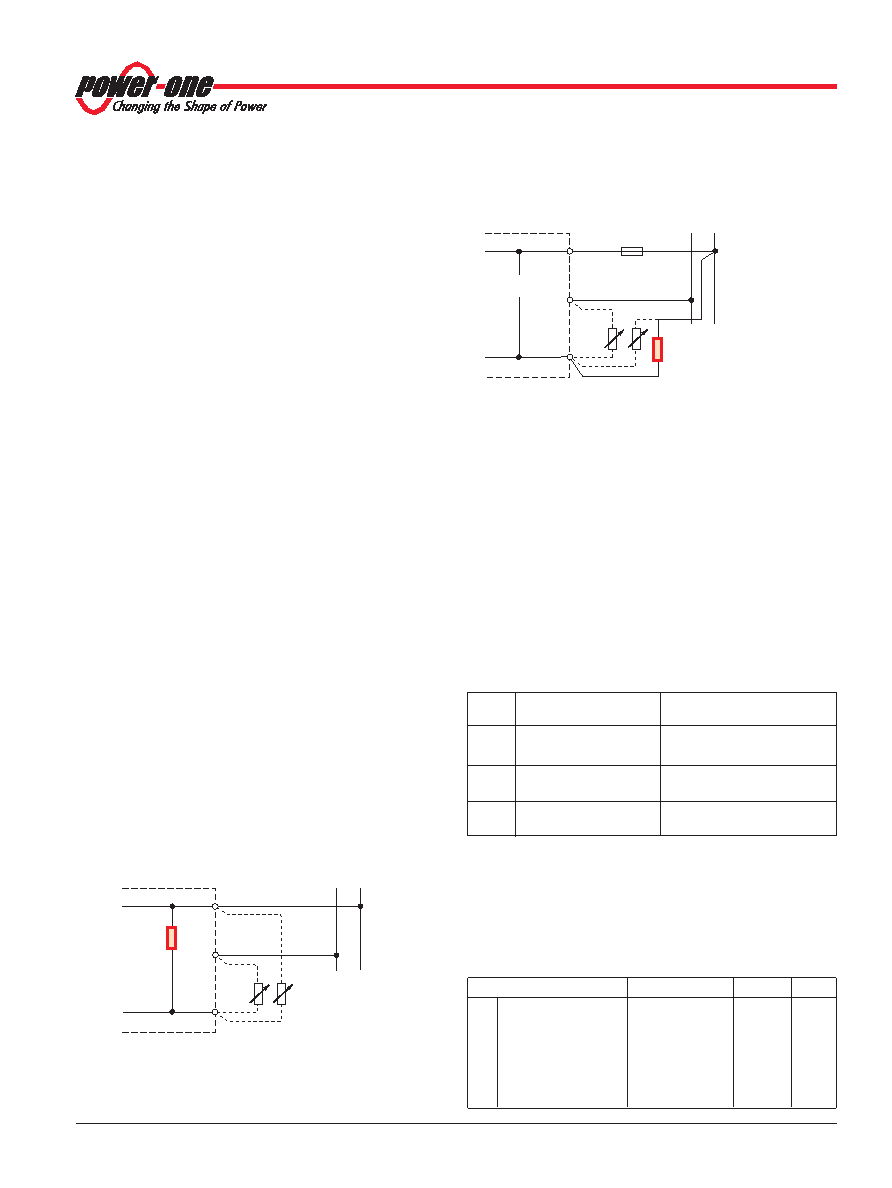
Fig. 20
Standard version; the power down circuitry monitors directly
Vo via Rint. Rext is not necessary.
Auxiliary Functions
Available Signals and Status Monitoring
The T Series exhibits an inhibit function as well as several
voltage monitoring and indicating functions for easy control
and surveillance of a complete customer-specific power supply
system. All the surveillance functions are driven from the
output. Consequently, it also operates, when the input voltage
is off, down to an output voltage of 5 V. The power consumption
of the surveillance circuit is typically 10 to 20 mA.
Available functions:
– Power Down
D
pin 30
D set
pin 32
– System Good
Sys In
pin 24
Sys Out
pin 26
– Inhibit/Vcr remote control
i/Vcr
pin 28
The status is indicated by 3 LEDs on the front panel:
– System
(OK)
green
– Vo
(OK)
green
– Error
red
Test sockets at the front panel allow easy measurement of Vo.
Power Down Function
The power down circuitry monitors Vo and changes the status
of output D (pin 30) from low to high impedance, when Vo falls
below the low threshold level, and changes back to low
impedance, when Vo exceeds the upper threshold level.
The rectifier versions have a relatively small hysteresis of 1 V,
the battery charger versions have a large hysteresis. The
upper threshold level is given, but the low threshold level is
externally adjustable at the D set pin 32. The Power Down
signal D (pin 30) can for example be used as a save data
signal, for low voltage warning, as a low-battery signal to avoid
deep discharge of the battery, or to prevent connected
converters from starting-up at a low bus voltage. For
application examples, see figures below using the signal D.
As it is driven from the output, the power pown circuitry
operates independently of the input voltage and the load
conditions, even if the converter is inhibited.
The standard version monitors Vo internally; see fig. below.
Vo+
Vo–
D set
T1000-7D
Rext
External
adjustment of the
threshold level Vt
R
43.2 k
(21.5 k
)
–
+
F
06051a
12
22
32
Fig. 21
Option D (D-set internally not connected); the power down
circuitry monitors the power bus decoupled by the fuse F.
With option D, the output voltage can be sensed externally, for
example, to monitor the system bus decoupled from the power
supplies by diodes or fuses. An external resistor of 43.2 k
1%
(21.5 k
for T1840) must be fitted into the sense line to the
bus; see fig. below.
Adjustment of the threshold level
With the resistor (Rext) connected to D set (pin 32) and Vo– (or
Vo+), the low threshold level can be increased (or decreased)
respectively; see fig. 20 and 21.
If the D set input is left open-circuit, the low threshold level of
the power down circuitry is factory-set to:
T12xx:
Vt set = 21 V
±0.2 V
T17xx:
Vt set = 42.5 V
±0.5 V
VT18xx:
Vt set = 32 V
±0.4 V
The approximate resistor values for given threshold levels can
be calculated from the table below:
The threshold level is adjusted for a DC output voltage. If in
operation a sinusoidal low frequency output ripple is
superimposed to the DC output voltage, it can be estimated
with Vov = Io/(2
π f Co), where Co is the internal output
capacitance.
Table 11: Typ. values for Rext for a given Vt value for LT1740
Characteristics
Conditions
Vt
Unit
Vt
Power down threshold
69 k
to Vo+
34.4
V
level,
106 k
to Vo+
36.4
set by Rext
254 k
to Vo+
39.5
left open-circuit
42.5
309 k
to Vo–
45.5
154 k
to Vo–
48.5
102 k
to Vo–
51.6
Vo+
Vo–
D set
Rext
Rint
–
+
06050a
43.2 k
(21.5 k
)
External adjustment of
the threshold level Vt
Table 10: Calculation of Rext
Model
Vt
>>>>> Vt set
Vt
<<<<< Vt set
(Rext connected to Vo–)
(Rext connected to Vo+)
T12xx
463.5
43.2 Vt – 463.5
Rext (Vt) = –––––––– [k
] Rext (Vt) = ––––––––––––– [k]
Vt –21.0
21.0 – Vt
T17xx
933
43.2 Vt – 933
Rext (Vt) = –––––––– [ k
] Rext (Vt) = ––––––––––––– [k]
Vt – 42.5
42.5 – Vt
T18xx
461
21.4Vt – 461
Rext (Vt) = –––––––– [ k
] Rext (Vt) = ––––––––––––– [k]
Vt – 32
32 – Vt
相关PDF资料 |
PDF描述 |
|---|---|
| LT1840-7Z | 1-OUTPUT 500 W AC-DC REG PWR SUPPLY MODULE |
| LT1740-7Z | 1-OUTPUT 500 W AC-DC REG PWR SUPPLY MODULE |
| LT1241MJ8 | 1 A SWITCHING CONTROLLER, 500 kHz SWITCHING FREQ-MAX, CDIP8 |
| LT1245MJ8 | 1 A SWITCHING CONTROLLER, 500 kHz SWITCHING FREQ-MAX, CDIP8 |
| LT1241CJ8 | 1 A SWITCHING CONTROLLER, 500 kHz SWITCHING FREQ-MAX, CDIP8 |
相关代理商/技术参数 |
参数描述 |
|---|---|
| LT1241 | 制造商:LINER 制造商全称:Linear Technology 功能描述:High Speed Current Mode Pulse Width Modulators |
| LT1241CJ8 | 制造商:未知厂家 制造商全称:未知厂家 功能描述:Current-Mode SMPS Controller |
| LT1241CN8 | 功能描述:IC REG CTRLR ISO PWM CM 8-DIP RoHS:否 类别:集成电路 (IC) >> PMIC - 稳压器 - DC DC 切换控制器 系列:- 标准包装:2,500 系列:- PWM 型:电流模式 输出数:1 频率 - 最大:500kHz 占空比:96% 电源电压:4 V ~ 36 V 降压:无 升压:是 回扫:无 反相:无 倍增器:无 除法器:无 Cuk:无 隔离:无 工作温度:-40°C ~ 125°C 封装/外壳:24-WQFN 裸露焊盘 包装:带卷 (TR) |
| LT1241CN8#PBF | 功能描述:IC REG CTRLR ISO PWM CM 8-DIP RoHS:是 类别:集成电路 (IC) >> PMIC - 稳压器 - DC DC 切换控制器 系列:- 标准包装:2,500 系列:- PWM 型:电流模式 输出数:1 频率 - 最大:500kHz 占空比:96% 电源电压:4 V ~ 36 V 降压:无 升压:是 回扫:无 反相:无 倍增器:无 除法器:无 Cuk:无 隔离:无 工作温度:-40°C ~ 125°C 封装/外壳:24-WQFN 裸露焊盘 包装:带卷 (TR) |
| LT1241CS8 | 功能描述:IC REG CTRLR ISO PWM CM 8-SOIC RoHS:否 类别:集成电路 (IC) >> PMIC - 稳压器 - DC DC 切换控制器 系列:- 标准包装:2,500 系列:- PWM 型:电流模式 输出数:1 频率 - 最大:500kHz 占空比:96% 电源电压:4 V ~ 36 V 降压:无 升压:是 回扫:无 反相:无 倍增器:无 除法器:无 Cuk:无 隔离:无 工作温度:-40°C ~ 125°C 封装/外壳:24-WQFN 裸露焊盘 包装:带卷 (TR) |
发布紧急采购,3分钟左右您将得到回复。