- 您现在的位置:买卖IC网 > PDF目录14048 > LT1425CS#TR (Linear Technology)IC REG FLYBK ISOLATED .2A 16SOIC PDF资料下载
参数资料
| 型号: | LT1425CS#TR |
| 厂商: | Linear Technology |
| 文件页数: | 12/20页 |
| 文件大小: | 0K |
| 描述: | IC REG FLYBK ISOLATED .2A 16SOIC |
| 标准包装: | 2,500 |
| 类型: | 回扫,隔离 |
| 输出数: | 1 |
| 输入电压: | 2.8 V ~ 20 V |
| PWM 型: | 电流模式 |
| 频率 - 开关: | 285kHz |
| 电流 - 输出: | 200mA |
| 同步整流器: | 无 |
| 工作温度: | 0°C ~ 100°C |
| 安装类型: | 表面贴装 |
| 封装/外壳: | 16-SOIC(0.154",3.90mm 宽) |
| 包装: | 带卷 (TR) |
| 供应商设备封装: | 16-SOIC |
�� �
�
�LT1425�
�APPLICATIO� N� S� I� N� FOR� M� ATIO� N�
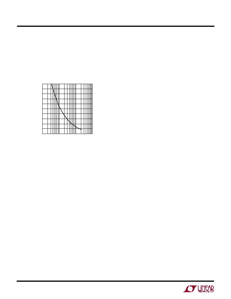
�amount� when� output� switch� current� is� zero.� Please� refer�
�to� Figure� 1� which� shows� nominal� reference� current� shift�
�at� zero� load� for� a� range� of� R� OCOMP� values.� Example:� for�
�a� load� compensation� resistor� of� 12k,� the� graph� indi-�
�cates� a� 1.0%� shift� in� reference� current.� The� R� FB� resistor�
�value� should� be� adjusted� down� by� about� 1.0%� to�
�restore� the� original� target� output� voltage.�
�2�
�1�
�integers,� e.g.,� 1:1,� 2:1,� 3:2,� etc.� can� be� employed� which�
�yield� more� freedom� in� setting� total� turns� and� mutual�
�inductance.� Turns� ratio� can� then� be� chosen� on� the� basis� of�
�desired� duty� cycle.� However,� remember� that� the� input�
�supply� voltage� plus� the� secondary-to-primary� referred�
�version� of� the� flyback� pulse� (including� leakage� spike)� must�
�not� exceed� the� allowed� output� switch� breakdown� rating.�
�Leakage� Inductance�
�Transformer� leakage� inductance� (on� either� the� primary� or�
�secondary)� causes� a� spike� after� output� switch� turn-off.�
�This� is� increasingly� prominent� at� higher� load� currents�
�where� more� stored� energy� must� be� dissipated.� In� many�
�cases� a� “snubber”� circuit� will� be� required� to� avoid� over-�
�voltage� breakdown� at� the� output� switch� node.� LTC’s�
�Application� Note� 19� is� a� good� reference� on� snubber�
�design.�
�0�
�1�
�10� 100�
�R� OCOMP� (k� ?� )�
�1000�
�In� situations� where� the� flyback� pulse� extends� beyond� the�
�enable� delay� time,� the� output� voltage� regulation� will� be�
�1425� F01�
�Figure� 1�
�In� less� critical� applications,� or� when� output� current�
�remains� relatively� constant,� the� load� compensation� func-�
�tion� may� be� deemed� unnecessary.� In� such� cases,� a�
�reduced� component� solution� may� be� obtained� as� follows:�
�Leave� the� R� OCOMP� node� open� (R� OCOMP� =� ∞� ),� and� replace�
�the� filter� capacitor� normally� on� the� R� CCOMP� node� with� a�
�short� to� ground.�
�TRANSFORMER� DESIGN� CONSIDERATIONS�
�Transformer� specification� and� design� is� perhaps� the� most�
�critical� part� of� applying� the� LT1425� successfully.� In� addi-�
�tion� to� the� usual� list� of� caveats� dealing� with� high� frequency�
�isolated� power� supply� transformer� design,� the� following�
�information� should� prove� useful.�
�Turns� Ratio�
�Note� that� due� to� the� use� of� an� R� FB� /R� REF� resistor� ratio� to� set�
�output� voltage,� the� user� has� relative� freedom� in� selecting�
�transformer� turns� ratio� to� suit� a� given� application.� In� other�
�words,� “screwball”� turns� ratios� like� “1.736:1.0”� can� scru-�
�pulously� be� avoided!� In� contrast,� simpler� ratios� of� small�
�12�
�affected� to� some� degree.� It� is� important� to� realize� that� the�
�feedback� system� has� a� deliberately� limited� input� range,�
�roughly� ±� 50mV� referred� to� the� R� REF� node,� and� this� works�
�to� the� user’s� advantage� in� rejecting� large,� i.e.,� higher�
�voltage� leakage� spikes.� In� other� words,� once� a� leakage�
�spike� is� several� volts� in� amplitude,� a� further� increase� in�
�amplitude� has� little� effect� on� the� feedback� system.� So� the�
�user� is� generally� advised� to� arrange� the� snubber� circuit� to�
�clamp� at� as� high� a� voltage� as� comfortably� possible,�
�observing� switch� breakdown,� such� that� leakage� spike�
�duration� is� as� short� as� possible.�
�As� a� rough� guide,� total� leakage� inductances� of� several�
�percent� (of� mutual� inductance)� or� less� may� require� a�
�snubber,� but� exhibit� little� to� no� regulation� error� due� to�
�leakage� spike� behavior.� Inductances� from� several� percent�
�up� to� perhaps� ten� percent� cause� increasing� regulation�
�error.�
�Severe� leakage� inductances� in� the� double� digit� percentage�
�range� should� be� avoided� if� at� all� possible� as� there� is� a�
�potential� for� abrupt� loss� of� control� at� high� load� current.�
�This� curious� condition� potentially� occurs� when� the� leak-�
�age� spike� becomes� such� a� large� portion� of� the� flyback�
�waveform� that� the� processing� circuitry� is� fooled� into�
�thinking� that� the� leakage� spike� itself� is� the� real� flyback�
�相关PDF资料 |
PDF描述 |
|---|---|
| 35MS54.7MEFCT54X5 | CAP ALUM 4.7UF 35V 20% RADIAL |
| V24B12C150BF3 | CONVERTER MOD DC/DC 12V 150W |
| 35MS54.7MEFCTZ4X5 | CAP ALUM 4.7UF 35V 20% RADIAL |
| V24B12C150BF | CONVERTER MOD DC/DC 12V 150W |
| LT1776IS8 | IC REG BUCK ADJ 0.7A 8SOIC |
相关代理商/技术参数 |
参数描述 |
|---|---|
| LT1425IS | 功能描述:IC REG FLYBK ISOLATED .2A 16SOIC RoHS:否 类别:集成电路 (IC) >> PMIC - 稳压器 - DC DC 开关稳压器 系列:- 标准包装:2,500 系列:- 类型:降压(降压) 输出类型:固定 输出数:1 输出电压:1.2V,1.5V,1.8V,2.5V 输入电压:2.7 V ~ 20 V PWM 型:- 频率 - 开关:- 电流 - 输出:50mA 同步整流器:是 工作温度:-40°C ~ 125°C 安装类型:表面贴装 封装/外壳:10-TFSOP,10-MSOP(0.118",3.00mm 宽)裸露焊盘 包装:带卷 (TR) 供应商设备封装:10-MSOP 裸露焊盘 |
| LT1425IS#PBF | 功能描述:IC REG FLYBK ISOLATED .2A 16SOIC RoHS:是 类别:集成电路 (IC) >> PMIC - 稳压器 - DC DC 开关稳压器 系列:- 产品培训模块:MIC23xxx HyperLight Load™ Regulators 标准包装:5,000 系列:HyperLight Load® 类型:降压(降压) 输出类型:固定 输出数:1 输出电压:1.8V 输入电压:2.7 V ~ 5.5 V PWM 型:混合物 频率 - 开关:4MHz 电流 - 输出:2A 同步整流器:是 工作温度:-40°C ~ 125°C 安装类型:表面贴装 封装/外壳:8-VFDFN 裸露焊盘,8-MLF? 包装:带卷 (TR) 供应商设备封装:8-MLF?(2x2) 产品目录页面:1094 (CN2011-ZH PDF) 其它名称:576-3303-2 |
| LT1425IS#TR | 功能描述:IC REG FLYBK ISOLATED .2A 16SOIC RoHS:否 类别:集成电路 (IC) >> PMIC - 稳压器 - DC DC 开关稳压器 系列:- 标准包装:2,500 系列:- 类型:降压(降压) 输出类型:固定 输出数:1 输出电压:1.2V,1.5V,1.8V,2.5V 输入电压:2.7 V ~ 20 V PWM 型:- 频率 - 开关:- 电流 - 输出:50mA 同步整流器:是 工作温度:-40°C ~ 125°C 安装类型:表面贴装 封装/外壳:10-TFSOP,10-MSOP(0.118",3.00mm 宽)裸露焊盘 包装:带卷 (TR) 供应商设备封装:10-MSOP 裸露焊盘 |
| LT1425IS#TRPBF | 功能描述:IC REG FLYBK ISOLATED .2A 16SOIC RoHS:是 类别:集成电路 (IC) >> PMIC - 稳压器 - DC DC 开关稳压器 系列:- 标准包装:2,500 系列:- 类型:降压(降压) 输出类型:固定 输出数:1 输出电压:1.2V,1.5V,1.8V,2.5V 输入电压:2.7 V ~ 20 V PWM 型:- 频率 - 开关:- 电流 - 输出:50mA 同步整流器:是 工作温度:-40°C ~ 125°C 安装类型:表面贴装 封装/外壳:10-TFSOP,10-MSOP(0.118",3.00mm 宽)裸露焊盘 包装:带卷 (TR) 供应商设备封装:10-MSOP 裸露焊盘 |
| LT1425ISPBF | 制造商:Linear Technology 功能描述:Sw. Regulator Isolated Flyback SOIC16 |
发布紧急采购,3分钟左右您将得到回复。