- 您现在的位置:买卖IC网 > PDF目录15981 > LT1510-5IGN#TR (Linear Technology)IC CHARGER BATT CONST V/I 16SSOP PDF资料下载
参数资料
| 型号: | LT1510-5IGN#TR |
| 厂商: | Linear Technology |
| 文件页数: | 13/16页 |
| 文件大小: | 0K |
| 描述: | IC CHARGER BATT CONST V/I 16SSOP |
| 标准包装: | 2,500 |
| 功能: | 充电管理 |
| 电池化学: | 锂离子,镍镉,镍氢 |
| 电源电压: | 6.2 V ~ 28 V |
| 工作温度: | -40°C ~ 85°C |
| 安装类型: | 表面贴装 |
| 封装/外壳: | 16-SSOP(0.154",3.90mm 宽) |
| 供应商设备封装: | 16-SSOP |
| 包装: | 带卷 (TR) |
�� �
�
�LT1510/LT1510-5�
�APPLICATIO� N� S� I� N� FOR� M� ATIO� N�
�(� )� .� 8� 4�
�[� ]� 2� 1� )(� .� )� =� 0� .� 17� W�
�(� )(� )� .� 8� 4� ?� ?� 1� +� 8� 30� .� 4� ?� ?�
�1� .� 2�
�55� (� )�
�(� 1� .� 2� )� (� 0� .� 35� )(� 8� .� 4� )� +�
�(� )(� )(� )�
�?� 10� ?� 10� 15� 1� .� 2� 200� kHz�
�=� =� 14� mA�
�Example:� V� IN� =� 15V,� V� BAT� =� 8.4V,� I� BAT� =� 1.2A;�
�P� BIAS� =� (� 3� .� 5� mA� )(� 15� )� +� 1� .� 5� mA� (� 8� .� 4� )�
�2�
�+� 15� 7� .� 5� mA� +� (� 0� .� 012�
�2� ?� ?�
�P� DRIVER� =� =� 0� .� 13� W�
�15�
�2�
�P� SW� =�
�15�
�?� 9� ?�
�?� ?�
�=� 0� .� 28� +� 0� .� 04� =� 0� .� 32� W�
�The� average� I� VX� required� is:�
�P� DRIVER� 0� .� 045W�
�V� X� 3� .� 3� V�
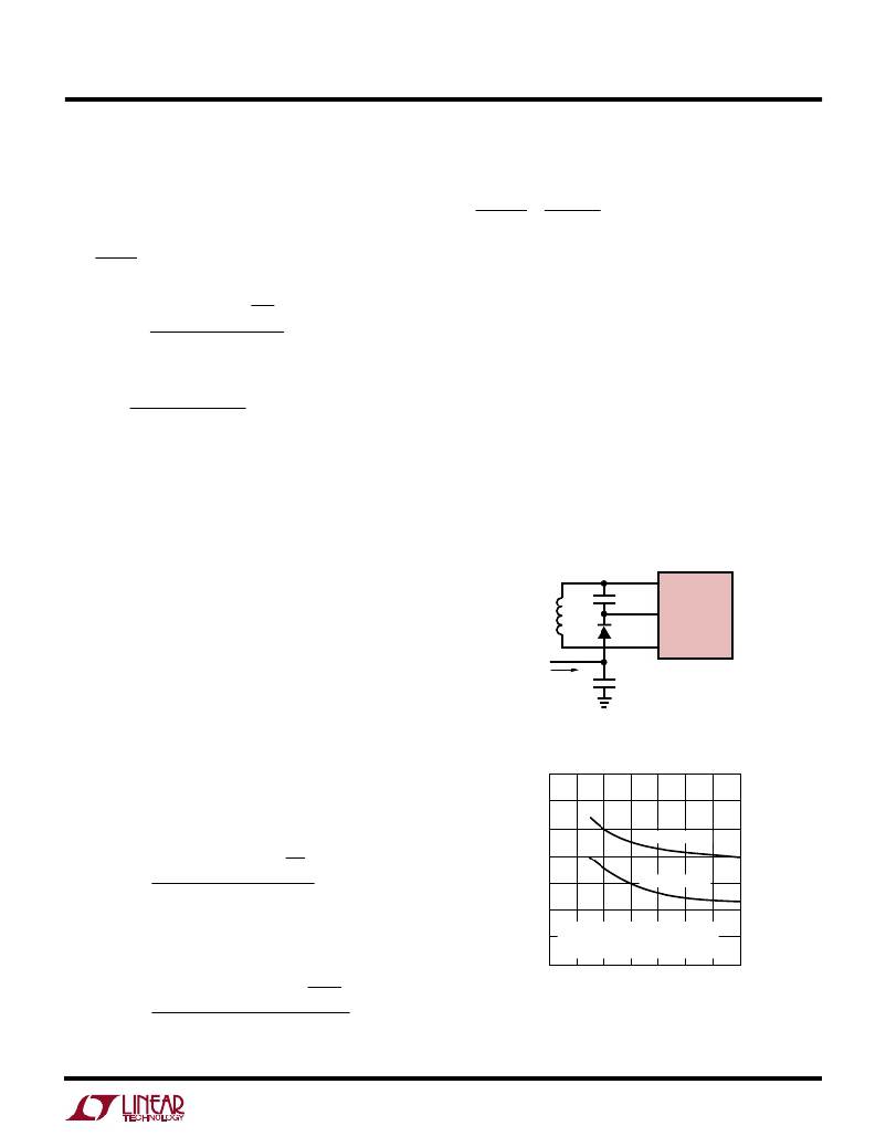
�Total� board� area� becomes� an� important� factor� when� the�
�area� of� the� board� drops� below� about� 20� square� inches.� The�
�graph� in� Figure� 9� shows� thermal� resistance� vs� board� area�
�for� 2-layer� and� 4-layer� boards.� Note� that� 4-layer� boards�
�have� significantly� lower� thermal� resistance,� but� both� types�
�show� a� rapid� increase� for� reduced� board� areas.� Figure� 10�
�shows� actual� measured� lead� temperature� for� chargers�
�operating� at� full� current.� Battery� voltage� and� input� voltage�
�will� affect� device� power� dissipation,� so� the� data� sheet�
�power� calculations� must� be� used� to� extrapolate� these�
�readings� to� other� situations.�
�Vias� should� be� used� to� connect� board� layers� together.�
�(� )(� )�
�P� SENSE� =� 0� .� 18� 1� .� 2�
�Total� power� in� the� IC� is:�
�2�
�=� 0� .� 26� W�
�Planes� under� the� charger� area� can� be� cut� away� from� the�
�rest� of� the� board� and� connected� with� vias� to� form� both� a�
�0.17� +� 0.13� +� 0.32+� 0.26� =� 0.88W�
�C1�
�SW�
�LT1510�
�Temperature� rise� will� be� (0.88W)(50� °� C/W)� =� 44� °� C.� This�
�assumes� that� the� LT1510� is� properly� heat� sunk� by� con-�
�L1�
�D2�
�BOOST�
�SENSE�
�necting� the� four� fused� ground� pins� to� the� expanded� traces�
�and� that� the� PC� board� has� a� backside� or� internal� plane� for�
�V� X�
�I� VX�
�+�
�10� μ� F�
�1510� F07�
�heat� spreading.�
�The� P� DRIVER� term� can� be� reduced� by� connecting� the� boost�
�diode� D2� (see� Figures� 2� and� 6� circuits)� to� a� lower� system�
�voltage� (lower� than� V� BAT� )� instead� of� V� BAT� (see� Figure� 8).�
�Then,�
�60�
�55�
�Figure� 8�
�(� )(� )(� )�
�V� X� ?� 1� +� X� ?�
�?�
�30� ?�
�P� DRIVER�
�=�
�?� V� ?�
�I� BAT� V� BAT�
�55� (� V� IN� )�
�50�
�45�
�40�
�35�
�2-LAYER BOARD�
�4-LAYER BOARD�
�For� example,� V� X� =� 3.3V,�
�30�
�S16,� MEASURED� FROM� AIR� AMBIENT�
�TO� DIE� USING� COPPER� LANDS� AS�
�SHOWN� ON� DATA� SHEET�
�(� )(� )(� )�
�1� .� 2� A� 8� .� 4� V� 3� .� 3� V� ?� 1� +�
�P� DRIVER�
�=�
�?�
�?�
�55� (� 15� V� )�
�3� .� 3� V� ?�
�30� ?� ?�
�=� 0� .� 045� W�
�25�
�0� 5� 10� 15� 20� 25� 30� 35�
�BOARD� AREA� (IN� 2� )�
�1510� F08�
�Figure� 9.� LT1510� Thermal� Resistance�
�13�
�相关PDF资料 |
PDF描述 |
|---|---|
| RSC07DRTH-S734 | CONN EDGECARD 14POS DIP .100 SLD |
| M3CMK-4018R | IDC CABLE - MKC40K/MC40M/MCG40K |
| LT1769CGN#TR | IC CHARGER BATT CONST V/I 28SSOP |
| MAX6752KA46+T | IC MPU/RESET CIRC SOT23-8 |
| VI-JVK-EZ-F3 | CONVERTER MOD DC/DC 40V 25W |
相关代理商/技术参数 |
参数描述 |
|---|---|
| LT-1510-610-006 | 制造商:Carling Technologies 功能描述:LT-SERIES TOGGLE SWITCH - Bulk |
| LT-1510-610-012 | 制造商:Carling Technologies 功能描述:LT-SERIES TOGGLE SWITCH - Bulk |
| LT-1510-610-125 | 制造商:Carling Technologies 功能描述:LT-SERIES TOGGLE SWITCH - Bulk |
| LT-1510-612-250 | 制造商:Carling Technologies 功能描述:LT-SERIES TOGGLE SWITCH - Bulk |
| LT1510614012 | 制造商:CARLING 功能描述:* |
发布紧急采购,3分钟左右您将得到回复。