- 您现在的位置:买卖IC网 > PDF目录69006 > LT1512CN8#TR (LINEAR TECHNOLOGY CORP) 2.7 A BATTERY CHARGE CONTROLLER, 580 kHz SWITCHING FREQ-MAX, PDIP8 PDF资料下载
参数资料
| 型号: | LT1512CN8#TR |
| 厂商: | LINEAR TECHNOLOGY CORP |
| 元件分类: | 稳压器 |
| 英文描述: | 2.7 A BATTERY CHARGE CONTROLLER, 580 kHz SWITCHING FREQ-MAX, PDIP8 |
| 封装: | 0.300 INCH, PLASTIC, DIP-8 |
| 文件页数: | 12/12页 |
| 文件大小: | 143K |
| 代理商: | LT1512CN8#TR |
LT1512
9
1512fa
APPLICATIONS INFORMATION
With ICHRG = 0.5A, VIN = 15V and VBAT = 8.2V, ICOUP = 0.43A
The recommended capacitor is a 2.2μF ceramic type from
Marcon or Tokin. These capacitors have extremely low ESR
and high ripple current ratings in a small package. Solid
tantalum units can be substituted if their ripple current
rating is adequate, but typical values will increase to 22μF
or more to meet the ripple current requirements.
Diode Selection
The switching diode should be a Schottky type to minimize
both forward and reverse recovery losses. Average diode
current is the same as output charging current , so this
will be under 1A. A 1A diode is recommended for most
applications, although smaller devices could be used at
reduced charging current. Maximum diode reverse voltage
will be equal to input voltage plus battery voltage.
Diode reverse leakage current will be of some concern
during charger shutdown. This leakage current is a direct
drain on the battery when the charger is not powered. High
currentSchottkydiodeshaverelativelyhighleakagecurrents
(2μA to 200μA) even at room temperature. The latest very-
low-forward devices have especially high leakage currents.
It has been noted that surface mount versions of some
Schottky diodes have as much as ten times the leakage of
their through-hole counterparts. This may be because a low
forward voltage process is used to reduce power dissipation
in the surface mount package. In any case, check leakage
specications carefully before making a nal choice for the
switching diode. Be aware that diode manufacturers want to
specify a maximum leakage current that is ten times higher
than the typical leakage. It is very difcult to get them to
specify a low leakage current in high volume production.
This is an on going problem for all battery charger circuits
and most customers have to settle for a diode whose typi-
cal leakage is adequate, but theoretically has a worst-case
condition of higher than desired battery drain.
Thermal Considerations
Care should be taken to ensure that worst-case conditions
do not cause excessive die temperatures. Typical thermal
resistance is 130°C/W for the S8 package but this number
will vary depending on the mounting technique (copper
area, air ow, etc).
Average supply current (including driver current) is:
ImA
VI
V
IN
BAT
CHRG
IN
=+
4
0 024
()(
)( .
)
Switch power dissipation is given by:
P
IR
V
SW
CHRG
SW
BAT
IN
BAT
IN
=
+
() (
)(
)
()
2
RSW = output switch ON resistance
Total power dissipation of the die is equal to supply current
times supply voltage, plus switch power:
PD(TOTAL) = (IIN)(VIN) + PSW
For VIN = 10V, VBAT = 8.2V, ICHRG = 0.5A, RSW = 0.65Ω
IIN = 4mA + 10mA = 14mA
PSW = 0.24W
PD = (0.014)(10) + 0.24 = 0.38W
The S8 package has a thermal resistance of 130°C/W.
(Contact factory concerning 16-lead fused-lead pack-
age with footprint approximately same as S8 package
and with lower thermal resistance.) Die temperature rise
will be (0.38W)(130°C/W) = 49°C. A maximum ambient
temperature of 60°C will give a die temperature of 60°C +
49°C = 109°C. This is only slightly less than the maximum
junction temperature of 125°C, illustrating the importance
of doing these calculations!
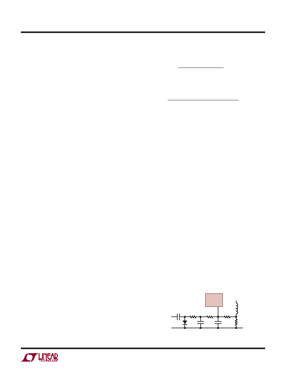
Programmed Charging Current
LT1512 charging current can be programmed with a PWM
signal from a processor as shown in Figure 5. C6 and D2
form a peak detector that converts a positive logic signal
to a negative signal. The average negative signal at the
+
C6
1μF
C7
10μF
C4
0.22μF
R3
1512 F05
L1B
IFB
LT1512
R5
4.02k
PWM
INPUT
≥1kHz
D2
R6
4.02k
R4
200Ω
+
Figure 5. Programming Charge Current
相关PDF资料 |
PDF描述 |
|---|---|
| LT1512IN8#TR | 2.7 A BATTERY CHARGE CONTROLLER, 580 kHz SWITCHING FREQ-MAX, PDIP8 |
| LT1512CN8#TRPBF | 2.7 A BATTERY CHARGE CONTROLLER, 580 kHz SWITCHING FREQ-MAX, PDIP8 |
| LT1512IN8#TRPBF | 2.7 A BATTERY CHARGE CONTROLLER, 580 kHz SWITCHING FREQ-MAX, PDIP8 |
| LT1681CSW | SWITCHING CONTROLLER, 500 kHz SWITCHING FREQ-MAX, PDSO20 |
| LT1681CSW#TR | SWITCHING CONTROLLER, 500 kHz SWITCHING FREQ-MAX, PDSO20 |
相关代理商/技术参数 |
参数描述 |
|---|---|
| LT1512CS8 | 功能描述:IC BATT CHRGR CONST I/V 8-SOIC RoHS:否 类别:集成电路 (IC) >> PMIC - 电池管理 系列:- 产品培训模块:Lead (SnPb) Finish for COTS Obsolescence Mitigation Program 标准包装:2,500 系列:- 功能:电池监控器 电池化学:碱性,锂离子,镍镉,镍金属氢化物 电源电压:1 V ~ 5.5 V 工作温度:-40°C ~ 85°C 安装类型:表面贴装 封装/外壳:SOT-23-6 供应商设备封装:SOT-6 包装:带卷 (TR) |
| LT1512CS8#PBF | 功能描述:IC BATT CHRGR CONST I/V 8-SOIC RoHS:是 类别:集成电路 (IC) >> PMIC - 电池管理 系列:- 其它有关文件:STC3100 View All Specifications 特色产品:STC3100 - Battery Monitor IC 标准包装:4,000 系列:- 功能:燃料,电量检测计/监控器 电池化学:锂离子(Li-Ion) 电源电压:2.7 V ~ 5.5 V 工作温度:-40°C ~ 85°C 安装类型:表面贴装 封装/外壳:8-TSSOP,8-MSOP(0.118",3.00mm 宽) 供应商设备封装:8-MiniSO 包装:带卷 (TR) 其它名称:497-10526-2 |
| LT1512CS8#TR | 功能描述:IC CHARGER BATT CONST V/I 8SOIC RoHS:否 类别:集成电路 (IC) >> PMIC - 电池管理 系列:- 产品培训模块:Lead (SnPb) Finish for COTS Obsolescence Mitigation Program 标准包装:2,500 系列:- 功能:电池监控器 电池化学:碱性,锂离子,镍镉,镍金属氢化物 电源电压:1 V ~ 5.5 V 工作温度:-40°C ~ 85°C 安装类型:表面贴装 封装/外壳:SOT-23-6 供应商设备封装:SOT-6 包装:带卷 (TR) |
| LT1512CS8#TRPBF | 功能描述:IC BATT CHRGR CONST I/V 8-SOIC RoHS:是 类别:集成电路 (IC) >> PMIC - 电池管理 系列:- 产品培训模块:Lead (SnPb) Finish for COTS Obsolescence Mitigation Program 标准包装:2,500 系列:- 功能:电池监控器 电池化学:碱性,锂离子,镍镉,镍金属氢化物 电源电压:1 V ~ 5.5 V 工作温度:-40°C ~ 85°C 安装类型:表面贴装 封装/外壳:SOT-23-6 供应商设备封装:SOT-6 包装:带卷 (TR) |
| LT1512CS8PBF | 制造商:Linear Technology 功能描述:LT1512CS8PBF |
发布紧急采购,3分钟左右您将得到回复。