- 您现在的位置:买卖IC网 > PDF目录15999 > LT1512CS8#TR (Linear Technology)IC CHARGER BATT CONST V/I 8SOIC PDF资料下载
参数资料
| 型号: | LT1512CS8#TR |
| 厂商: | Linear Technology |
| 文件页数: | 9/12页 |
| 文件大小: | 0K |
| 描述: | IC CHARGER BATT CONST V/I 8SOIC |
| 标准包装: | 2,500 |
| 功能: | 充电管理 |
| 电池化学: | 所有电池类型 |
| 电源电压: | 2.7 V ~ 25 V |
| 工作温度: | 0°C ~ 70°C |
| 安装类型: | 表面贴装 |
| 封装/外壳: | 8-SOIC(0.154",3.90mm 宽) |
| 供应商设备封装: | 8-SOIC |
| 包装: | 带卷 (TR) |
�� �
�
�LT1512�
�APPLICATIONS� INFORMATION�
�With� I� CHRG� =� 0.5A,� V� IN� =� 15V� and� V� BAT� =� 8.2V,� I� COUP� =� 0.43A�
�Average� supply� current� (including� driver� current)� is:�
�(� V� BAT� CHRG� )(� 0� .� 024� )�
�Therecommendedcapacitorisa2.2μFceramictypefrom�
�Marcon� or� Tokin.� These� capacitors� have� extremely� low� ESR�
�and� high� ripple� current� ratings� in� a� small� package.� Solid�
�I� IN� =� 4� mA� +�
�)(� I�
�V� IN�
�+� V� )(� V�
�(� I� CHRG� SW� BAT� IN� BAT� )�
�)� (� R�
�)(� V�
�tantalum units can be substituted if their ripple current�
�rating� is� adequate,� but� typical� values� will� increase� to� 22μF�
�or� more� to� meet� the� ripple� current� requirements.�
�Diode� Selection�
�The� switching� diode� should� be� a� Schottky� type� to� minimize�
�both� forward� and� reverse� recovery� losses.� Average� diode�
�current� is� the� same� as� output� charging� current� ,� so� this�
�will� be� under� 1A.� A� 1A� diode� is� recommended� for� most�
�applications,� although� smaller� devices� could� be� used� at�
�reduced� charging� current.� Maximum� diode� reverse� voltage�
�will� be� equal� to� input� voltage� plus� battery� voltage.�
�Diode� reverse� leakage� current� will� be� of� some� concern�
�during� charger� shutdown.� This� leakage� current� is� a� direct�
�drain� on� the� battery� when� the� charger� is� not� powered.� High�
�current� Schottky� diodes� have� relatively� high� leakage� currents�
�(2μA� to� 200μA)� even� at� room� temperature.� The� latest� very-�
�low-forward� devices� have� especially� high� leakage� currents.�
�It� has� been� noted� that� surface� mount� versions� of� some�
�Schottky� diodes� have� as� much� as� ten� times� the� leakage� of�
�their� through-hole� counterparts.� This� may� be� because� a� low�
�forward� voltage� process� is� used� to� reduce� power� dissipation�
�in� the� surface� mount� package.� In� any� case,� check� leakage�
�speci?cations� carefully� before� making� a� ?nal� choice� for� the�
�switching� diode.� Be� aware� that� diode� manufacturers� want� to�
�specify� a� maximum� leakage� current� that� is� ten� times� higher�
�than� the� typical� leakage.� It� is� very� dif?cult� to� get� them� to�
�specify� a� low� leakage� current� in� high� volume� production.�
�This� is� an� on� going� problem� for� all� battery� charger� circuits�
�and� most� customers� have� to� settle� for� a� diode� whose� typi-�
�cal� leakage� is� adequate,� but� theoretically� has� a� worst-case�
�condition� of� higher� than� desired� battery� drain.�
�Thermal� Considerations�
�Switch� power� dissipation� is� given� by:�
�2�
�P� SW� =�
�(� V� IN� )� 2�
�R� SW� =� output� switch� ON� resistance�
�Total� power� dissipation� of� the� die� is� equal� to� supply� current�
�times� supply� voltage,� plus� switch� power:�
�P� D(TOTAL)� =� (I� IN� )(V� IN� )� +� P� SW�
�For� V� IN� =� 10V,� V� BAT� =� 8.2V,� I� CHRG� =� 0.5A,� R� SW� =� 0.65Ω�
�I� IN� =� 4mA� +� 10mA� =� 14mA�
�P� SW� =� 0.24W�
�P� D� =� (0.014)(10)� +� 0.24� =� 0.38W�
�The� S8� package� has� a� thermal� resistance� of� 130°C/W.�
�(Contact� factory� concerning� 16-lead� fused-lead� pack-�
�age� with� footprint� approximately� same� as� S8� package�
�and� with� lower� thermal� resistance.)� Die� temperature� rise�
�will� be� (0.38W)(130°C/W)� =� 49°C.� A� maximum� ambient�
�temperature� of� 60°C� will� give� a� die� temperature� of� 60°C� +�
�49°C� =� 109°C.� This� is� only� slightly� less� than� the� maximum�
�junction� temperature� of� 125°C,� illustrating� the� importance�
�of� doing� these� calculations!�
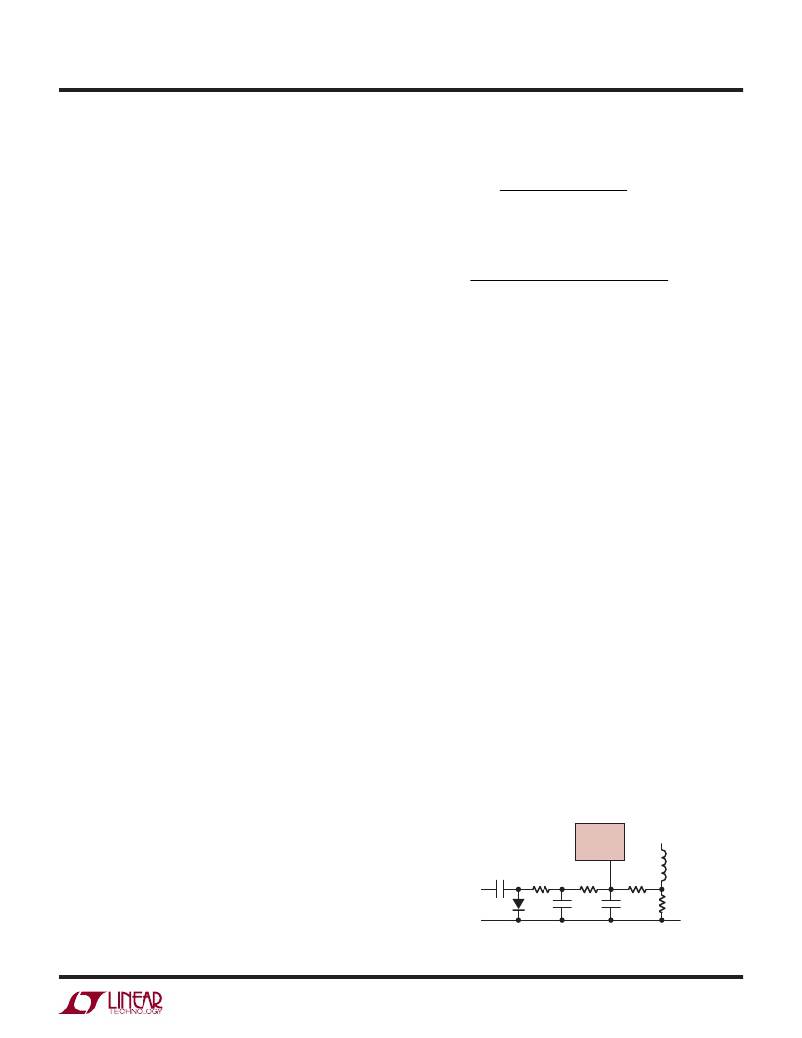
�Programmed� Charging� Current�
�LT1512� charging� current� can� be� programmed� with� a� PWM�
�signal� from� a� processor� as� shown� in� Figure� 5.� C6� and� D2�
�form� a� peak� detector� that� converts� a� positive� logic� signal�
�to� a� negative� signal.� The� average� negative� signal� at� the�
�LT1512�
�I� FB�
�Care� should� be� taken� to� ensure� that� worst-case� conditions�
�do� not� cause� excessive� die� temperatures.� Typical� thermal�
�resistance� is� 130°C/W� for� the� S8� package� but� this� number�
�PWM�
�INPUT�
�≥1kHz�
�C6�
�1μF�
�R5�
�4.02k�
�D2�
�+�
�R6�
�4.02k�
�C7�
�10μF�
�R4�
�200Ω�
�C4�
�0.22μF�
�L1B�
�R3�
�will� vary� depending� on� the� mounting� technique� (copper�
�area,� air� ?ow,� etc).�
�1512� F05�
�Figure� 5.� Programming� Charge� Current�
�1512fa�
�9�
�相关PDF资料 |
PDF描述 |
|---|---|
| VI-JVR-EY-S | CONVERTER MOD DC/DC 7.5V 50W |
| M3DDK-6018J | IDC CABLE - MKR60K/MC60G/MKR60K |
| FRN0.50TB100 | TRACER 1/2" BLACK W/WHITE 100' |
| 415-0009-024 | CABLE SMB-RA/SMB-RA 24" RG-179 |
| MAX6841FUKD3+T | IC MPU/RESET CIRC SOT23-5 |
相关代理商/技术参数 |
参数描述 |
|---|---|
| LT1512I | 制造商:LINER 制造商全称:Linear Technology 功能描述:SEPIC Constant-Current/ Constant-Voltage Battery Charger |
| LT1512IGN | 功能描述:IC BATT CHRGR CONST I/V 16-SSOP RoHS:否 类别:集成电路 (IC) >> PMIC - 电池管理 系列:- 产品培训模块:Lead (SnPb) Finish for COTS Obsolescence Mitigation Program 标准包装:2,500 系列:- 功能:电池监控器 电池化学:碱性,锂离子,镍镉,镍金属氢化物 电源电压:1 V ~ 5.5 V 工作温度:-40°C ~ 85°C 安装类型:表面贴装 封装/外壳:SOT-23-6 供应商设备封装:SOT-6 包装:带卷 (TR) |
| LT1512IGN#PBF | 功能描述:IC BATT CHRGR CONST I/V 16-SSOP RoHS:是 类别:集成电路 (IC) >> PMIC - 电池管理 系列:- 产品培训模块:Lead (SnPb) Finish for COTS Obsolescence Mitigation Program 标准包装:2,500 系列:- 功能:电池监控器 电池化学:碱性,锂离子,镍镉,镍金属氢化物 电源电压:1 V ~ 5.5 V 工作温度:-40°C ~ 85°C 安装类型:表面贴装 封装/外壳:SOT-23-6 供应商设备封装:SOT-6 包装:带卷 (TR) |
| LT1512IGN#TR | 功能描述:IC CHARGER BATT CONST V/I 16SSOP RoHS:否 类别:集成电路 (IC) >> PMIC - 电池管理 系列:- 产品培训模块:Lead (SnPb) Finish for COTS Obsolescence Mitigation Program 标准包装:2,500 系列:- 功能:电池监控器 电池化学:碱性,锂离子,镍镉,镍金属氢化物 电源电压:1 V ~ 5.5 V 工作温度:-40°C ~ 85°C 安装类型:表面贴装 封装/外壳:SOT-23-6 供应商设备封装:SOT-6 包装:带卷 (TR) |
| LT1512IGN#TRPBF | 功能描述:IC BATT CHRGR CONST I/V 16-SSOP RoHS:是 类别:集成电路 (IC) >> PMIC - 电池管理 系列:- 产品培训模块:Lead (SnPb) Finish for COTS Obsolescence Mitigation Program 标准包装:2,500 系列:- 功能:电池监控器 电池化学:碱性,锂离子,镍镉,镍金属氢化物 电源电压:1 V ~ 5.5 V 工作温度:-40°C ~ 85°C 安装类型:表面贴装 封装/外壳:SOT-23-6 供应商设备封装:SOT-6 包装:带卷 (TR) |
发布紧急采购,3分钟左右您将得到回复。