- 您现在的位置:买卖IC网 > PDF目录377707 > LT1534-1 (Linear Technology Corporation) RADIATION HARDENED HIGH EFFICIENCY, 5 AMP SWITCHING REGULATORS PDF资料下载
参数资料
| 型号: | LT1534-1 |
| 厂商: | Linear Technology Corporation |
| 元件分类: | 基准电压源/电流源 |
| 英文描述: | RADIATION HARDENED HIGH EFFICIENCY, 5 AMP SWITCHING REGULATORS |
| 中文描述: | 抗辐射高效,5安培开关稳压器 |
| 文件页数: | 12/16页 |
| 文件大小: | 222K |
| 代理商: | LT1534-1 |
12
LT1534/LT1534-1
APPLICATIO
S I
FOR
ATIO
U
Input Capacitor
The ESR of this capacitor acts with high frequency current
components to produce much of the conducted noise of
the switcher. Values of 1
μ
F to 47
μ
F are typical with ESR
less than 0.3
. Place the capacitor close to the IC and
inductor.
The input capacitor can see a high surge current when a
battery of high capacitance source is connected “live.”
Some solid tantalum capacitors can fail under this con-
dition. Several manufacturers have developed a line of
solid tantalum capacitors specially tested for surge capa-
bility (e.g., AVX TPS series). However, even these units
may fail if the input voltage approaches the maximum
voltage rating of the capacitor. AVX recommends derat-
ing capacitor voltage by 2:1 for high surge applications.
W
U
U
Fast Voltage Slew Edges
A very fast voltage slew under certain operating conditions
may produce ringing on the COL voltage waveform. While
there is small harmonic energy in this, it can be eliminated
by placing an RC network of 10
in series with 1000pF
from the COL pin to ground.
Switching Diodes
In general, switching diodes should be Schottky diodes
such as 1N5817-19 or MBR320-330.
Choosing the Inductor
For a boost converter, inductor selection involves trade-
offs of size, maximum output power, transient response
and filtering characteristics. Higher inductor values pro-
vide more output power and lower input ripple. However,
they are physically larger and can impede transient re-
sponse. Low inductor values have high magnetizing cur-
rent, which can reduce maximum power and increase
input current ripple.
The following procedure can be used to handle these
trade-offs:
1. Assume that the average inductor current for a boost
converter is equal to load current times V
OUT
/V
IN
and
decide whether the inductor must withstand continu-
ous overload conditions. If average inductor current at
maximum load current is 0.5A, for instance, a 0.5A
inductor may not survive a continuous 1.5A overload
condition. Also be aware that boost converters are not
short-circuit protected, and under output short condi-
tions, only the available current of the input supply
limits inductor current.
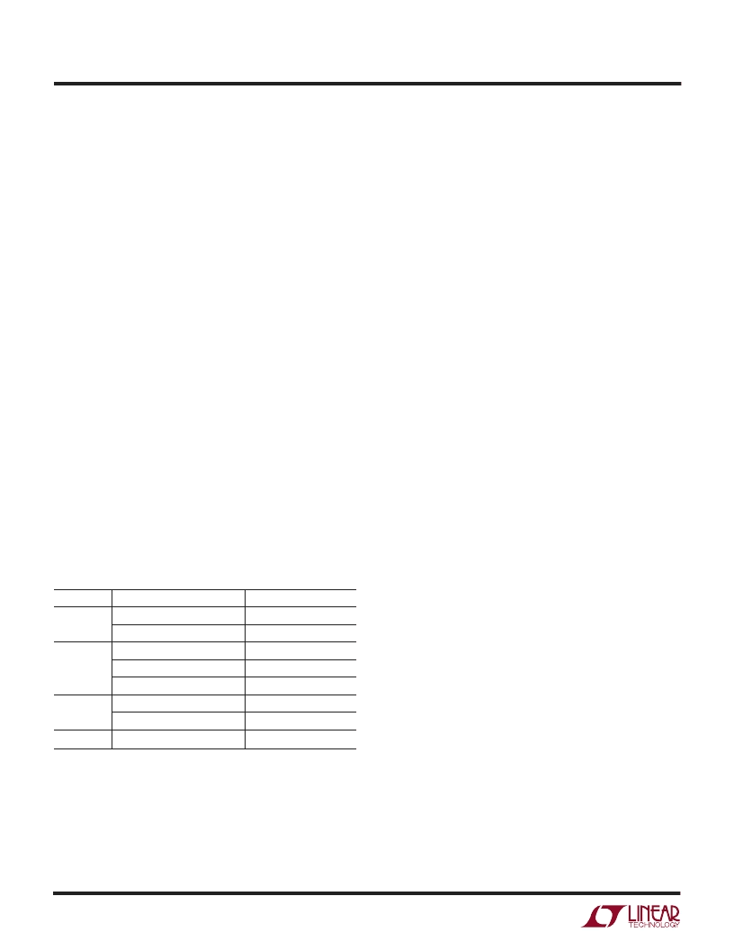
Output Filter Capacitor
Output capacitors are usually chosen on the basis of ESR
since this will determine output ripple. However, low ESR
is also needed for low output noise and this will typically
be the tougher requirement. Typically required ESR will be
less than 0.2
. Typical capacitance values are in the 47
μ
F
to 500
μ
F range. Again keep connection length as short as
possible. Table 1 shows some typical surface mount
capacitors.
Table 1
SIZE
E CASE
CAPACITOR
AVX TPS, Sprague 593D
AVX TAJ
AVX TPS, Sprague 593D
AVX TAJ
Panasonic CD
AVX TPS
AVX TAJ
AVX TAJ
ESR (MAX
)
0.1 to 0.3
0.7 to 0.9
0.1 to 0.3
0.9 to 2.0
0.05 to 0.18
0.2 (Typ)
1.8 to 3.0
2.5 to 10
D CASE
C CASE
B CASE
相关PDF资料 |
PDF描述 |
|---|---|
| LT1534CS-1 | RADIATION HARDENED HIGH EFFICIENCY, 5 AMP SWITCHING REGULATORS |
| LT1534 | Octal Bus Transceivers 20-PDIP 0 to 70 |
| LT1534C | RADIATION HARDENED HIGH EFFICIENCY, 5 AMP SWITCHING REGULATORS |
| LT1534CS | RADIATION HARDENED HIGH EFFICIENCY, 5 AMP SWITCHING REGULATORS |
| LT1534I | RADIATION HARDENED HIGH EFFICIENCY, 5 AMP SWITCHING REGULATORS |
相关代理商/技术参数 |
参数描述 |
|---|---|
| LT-1534-501-024 | 制造商:Carling Technologies 功能描述:LT-SERIES TOGGLE SWITCH - Bulk |
| LT-1534-510-012 | 制造商:Carling Technologies 功能描述:LT-SERIES TOGGLE SWITCH - Bulk |
| LT-1534-510-024 | 制造商:Carling Technologies 功能描述:LT-SERIES TOGGLE SWITCH - Bulk |
| LT-1534-510-125 | 制造商:Carling Technologies 功能描述:LT-SERIES TOGGLE SWITCH - Bulk |
| LT-1534-520-012 | 制造商:Carling Technologies 功能描述:LT-SERIES TOGGLE SWITCH - Bulk |
发布紧急采购,3分钟左右您将得到回复。